Kia Picanto (JA): Drive Belt System / Crankshaft Damper Pulley
Kia Picanto (JA) 2017-2026 Service & Repair Manual / Engine Mechanical System / Drive Belt System / Crankshaft Damper Pulley
Repair procedures
| Removal and Installation |
| 1. | Remove the engine room under cover and RH side cover.
(Refer to Engine and Transaxle Assembly - "Engine Room Under Cover")
|
| 2. | Remove the drive belt.
(Refer to Drive Belt System - "Drive Belt")
|
| 3. | Remove the RH side front wheel.
(Refer to Suspension System - "Wheel")
|
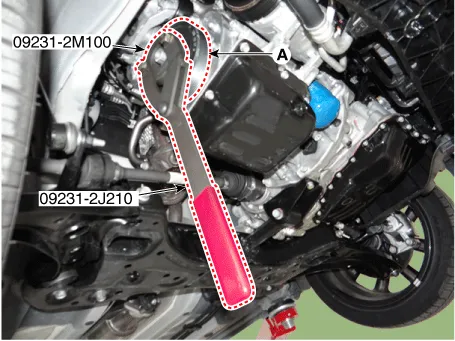
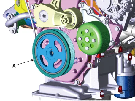
| 4. | Remove the crankshaft damper pulley.
|
| 5. | Install in the reverse order of removal. |
| Inspection |
Check
the crankshaft damper pulley for vibration during rotation, and oil or
dust deposit on V-ribbed part. Replace if necessary.
Repair procedures Removal and Installation 1.Remove the engine room under cover. (Refer to Engine and Transaxle Assembly - "Engine Room Under Cover") 2.
Other information:
Kia Picanto (JA) 2017-2026 Service & Repair Manual: Headlamp Leveling Switch
Schematic diagrams Circuit Diagram Repair procedures Removal 1.Disconnect the negative (-) battery terminal. 2.Remove the crash pad lower panel. (Refer to Body - "Crash Pad Lower Panel") 3.Remove the crash pad side switch (A) after loosening the mounting screws.
Kia Picanto (JA) 2017-2026 Service & Repair Manual: Rear Washer Motor
Repair procedures Inspection 1.With the washer motor connected to the reservoir tank, fill the reservoir tank with water. Before filling the reservoir tank with water, check the filter for foreign material or contamination.
Categories
- Manuals Home
- Kia Picanto Owners Manual
- Kia Picanto Service Manual
- Fuel Delivery System
- Engine Control / Fuel System
- Battery
- New on site
- Most important about car

Copyright © 2026 www.kpicanto.com - 0.0221