Kia Picanto (JA): Manual Transaxle Control System / Control Cable
Components and components location
| Components |
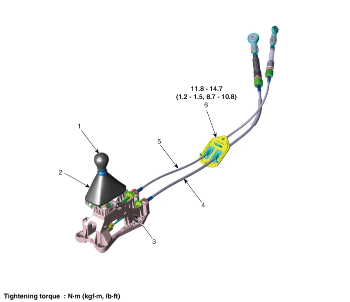
| 1. Knob 2. Boots 3. Shift lever assembly | 4. Shift cable 5. Select cable 6. Retainer |
Repair procedures
| Inspection |
| 1. | Check for proper operation of control shaft lever when operated (1st, 2nd, 3rd, 4th, 5th, R). |
| 2. | If the gear feels stiff, adjust the control cable length again.
(Refer to Manual Control System - "Control Cable")
|
| Adjustment |
| 1. | Move the shift lever to 4th gear. |
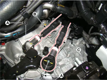
| 2. | Remove the control cable (B) from the control shaft after removing the snap pins (A).
|

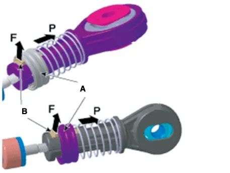
| 3. | After pulling the holder (A) in the direction of the "P", pull the lock (B) in the direction of the "F".
|
| 4. | Insert the snap pins (A).
|

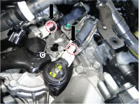
| 5. | Push the lock (C) after installing the control cable to the control shaft.
|
| Removal |
| 1. | Move the shift lever to 4th gear.ove the battery and battery tray. |
| 2. | Remove the battery and battery tray.
G 1.0 T-GDI KAPPA (Refer to Engine Electrical System - "Battery")
|
| 3. | Remove the control cable.
|
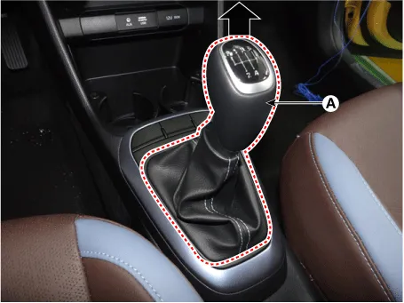
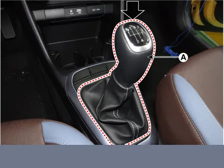
| 4. | Remove the knob (A) by pulling it in the direction of arrow.
|
| 5. | Remove the floor console assembly.
(Refer to Body “Floor Console Assembly”)
|
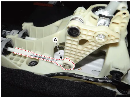
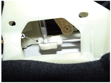
| 6. | Remove the snap pin (A) and then remove the select cable from the shift lever pin.
|
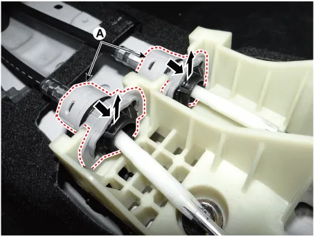
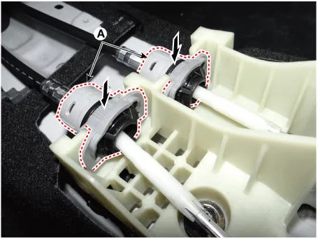
| 7. | Remove the cable sockets (A) from the shift lever.
|
| 8. | Remove the shift lever (A).
|

| 9. | Remove
the shift cable retainer (A) after loosening the nuts. Then, remove the
shift cable by pulling it toward the vehicle interior.
|
| Installation |
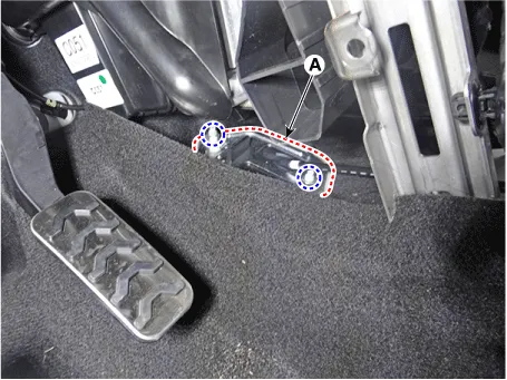
| 1. | Install the shift cable retainer by tightening nuts (A).
|
| 2. | Install the shift cable (A).
|
| 3. | Install the cable sockets (A).
|
| 4. | Install the select cable to the lever pin and then insert the snap pin (A).
|
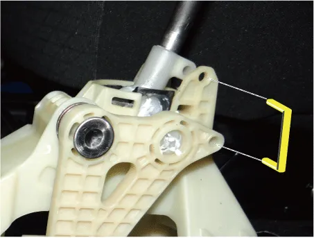
| 5. | Check that the shift lever and control shaft are placed in the "4th" position and then install the 4th fixing pin.
|
| 6. | Install the control cable.
|
| 7. | Remove the 4th fixing pin (A).
|
| 8. | Install the floor console assembly.
(Refer to Body - "Floor Console Assembly")
|
| 9. | Install the knob (A) by pressing it in the direction of arrow.
|
| 10. | Install the battery and battery tray.
G 1.0 T-GDI KAPPA (Refer to Engine Electrical System - "Battery")
|
Components and components location Components 1. Knob 2. Boots 3. Shift lever assembly 4. Shift cable 5. Select cable Repair procedures Inspection 1.
Other information:
Kia Picanto (JA) 2017-2026 Service & Repair Manual: Immobilizer System
Schematic diagrams Circuit Diaram Description and operation Description The immobilizer system will disable the vehicle unless the proper ignition key is used, in addition to the currently available anti-theft systems such as car alarms, the immobilizer system aims to drastically reduce the rate of auto theft.
Kia Picanto (JA) 2017-2026 Service & Repair Manual: Power Door Lock Switch
Repair procedures Inspection 1.Check for continuity between the terminals. If there is an abnormality, replace the switch. Removal • When removing with a flat-tip screwdriver or remover, wrap protective tape around the tools to prevent damage to components.
Categories
- Manuals Home
- Kia Picanto Owners Manual
- Kia Picanto Service Manual
- Battery
- Timing Chain
- Engine Mechanical System
- New on site
- Most important about car
