Kia Picanto (JA): ISG (Idle Stop & Go) System / Clutch switch
Specifications
| Specifications |
|
Item
|
Specifications
|
| Working voltage | DC 12.5V |
| Operating force | Initial position : 0.25 ± 0.15 N (0.025 ± 0.015 kg, 0.056 ± 0.034 lb) |
| Full position : 0.8 ± 0.2 N (0.08 ± 0.02 kgf, 0.579 ± 0.014 lb-ft) | |
| Working temperature | -40°C to 80°C (-40°F to 176°F) |
Repair procedures
| Inspection |
| 1. | Remove the clutch & ignition lock switch. |
| 2. | Rotate the switch lever to the direction of the arrow to check the operating point (A).
|


| Removal |
| 1. | Turn ignition switch OFF and disconnect the negative (-) battery cable. |
| 2. | Remove the crash pad lower panel.
(Refer to Body - "Crash Pad Lower Panel")
|
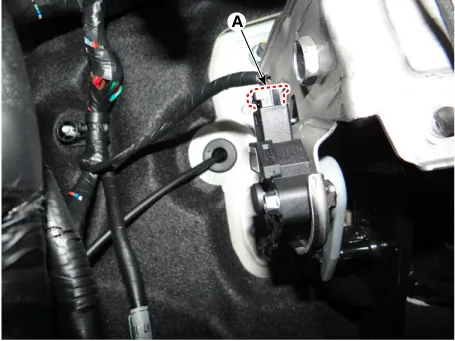
| 3. | Disconnect the cluch switch & ignition lock swtich connector (A).
|
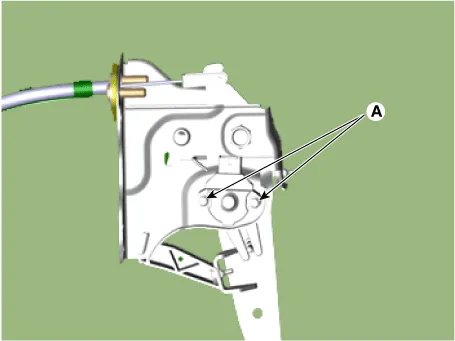
| 4. | Loosen the bolts (A) and then remove the ignition lock switch & clutch switch.
|
| Installation |
| 1. | Install in the reverse order of removal.
|


Description and operation Description The hood switch is included as the influencing factors in the calculation of the ISG function. If the hood is open, the engine must not be started or stopped by the ISG function for safety reasons.
Components and components location Components Location Fuel Tank & Filler-Neck Assembly 1. Fuel Tank 2. Fuel Pump 3 Fuel Filter 4.
Other information:
Kia Picanto (JA) 2017-2026 Service & Repair Manual: Power Window Switch
Components and components location Components Driver Power Window Switch Connector Pin Information [All Manual / Auto Down Type] (LHD) No. Description No.
Kia Picanto (JA) 2017-2026 Service & Repair Manual: Climate Control Air Filtar
Description and operation Description This has particle filter which eliminates foreign materials and odor. The particle filter includes odor filter as well as conventional dust filter to ensure comfortable interior environment. Repair procedures Replacement 1.
Categories
- Manuals Home
- Kia Picanto Owners Manual
- Kia Picanto Service Manual
- Cooling System
- Thermostat
- Battery
- New on site
- Most important about car
