Kia Picanto (JA): Clutch System / Clutch Cover And Disc
Kia Picanto (JA) 2017-2026 Service & Repair Manual / Clutch System / Clutch System / Clutch Cover And Disc
Components and components location
| Components |
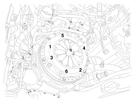
[Kappa 1.0 MPI / FFV, Kappa 1.2 MPI]

| 1. Clutch disc assembly 2. Clutch cover assembly 3. Clutch release bearing 4. Clutch release lever assembly | 5. Return spring 6. Clutch release fork 7. Return clip |
[Kappa 1.0 T-GDI]

| 1. Clutch release fork 2. Clutch cover assembly | 3. Clutch disk assembly 4. Clutch release bearing |
Repair procedures
| Removal |
| 1. | Remove the transaxle assembly.
G 1.0 MPI KAPPA (Refer to Manual Transaxle System - "Manual Transaxle")
G 1.0 T-GDI KAPPA (Refer to Manual Transaxle System - "Manual Transaxle")
G 1.2 MPI KAPPA (Refer to Manual Transaxle System - "Manual Transaxle")
F 1.0 KAPPA FFV (Refer to Manual Transaxle System - "Manual Transaxle")
|
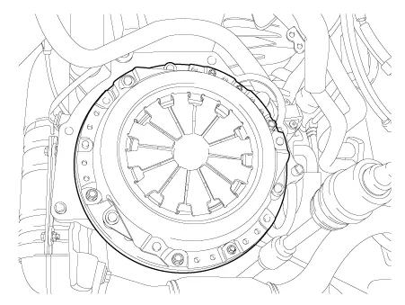
| 2. | Remove the clutch cover bolts. Be careful not to be bent or twist bolts. Loosen bolts in diagonal directions.
|
| Inspection |
| Clutch cover assembly |
| 1. | Check the diaphragm spring end for wear and uneven height. |
| 2. | Check the pressure plate surface for wear, cracks and color change. |
| 3. | Check the rivets for looseness and replace the clutch cover assembly if necessary. |
| Clutch disc assembly |
| 1. |
Check the clutch facing for loose rivets, uneven contact, deterioration
due to seizure, adhesion of oil, or grease, and replace the clutch disc
if defective. |
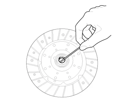
| 2. | Check for the torsion spring play and damage and if defective, replace the clutch disc. |
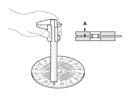
| 3. |
Measure the depth from a clutch lining surface to a rivet. If the
measured value is less than the specification below, replace it.
|
| Installation |
If reinstalling used cover, the cover should be installed with its clutch disc as a set. |

| 1. | Apply grease on a disc spline part and transaxle input shaft spline part as required.
|
| 2. | Make sure about the direction of the clutch disc when installing.
|

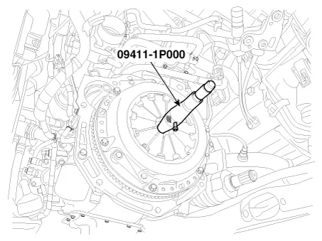
| 3. | Install the clutch disc and the cover with SST (A: 09411-1P000).
|
| 4. | Install the clutch cover bolts. Not to be bent or twisted, Tighten them in diagonal directions
|
| 5. | Install the transaxle assembly.
G 1.0 MPI KAPPA (Refer to Manual Transaxle System - "Manual Transaxle")
G 1.0 T-GDI KAPPA (Refer to Manual Transaxle System - "Manual Transaxle")
G 1.2 MPI KAPPA (Refer to Manual Transaxle System - "Manual Transaxle")
F 1.0 KAPPA FFV (Refer to Manual Transaxle System - "Manual Transaxle")
|
Specifications Specifications Item Specifications Working voltage DC 12.5V Operating force Initial position : 0.
Other information:
Kia Picanto (JA) 2017-2026 Service & Repair Manual: Seat Heater Switch
Components and components location Components 1. Driver side seat heater switch 2. Passenger side seat heater switch Schematic diagrams Circuit Diagram Repair procedures Removal 1. Disconnect the negative (-) battery terminal.
Kia Picanto (JA) 2017-2026 Service & Repair Manual: Sunroof
C
Categories
- Manuals Home
- Kia Picanto Owners Manual
- Kia Picanto Service Manual
- Battery
- Body Electrical System
- Front Disc Brake
- New on site
- Most important about car

Copyright © 2026 www.kpicanto.com - 0.0179