
Kia Picanto (JA): Intake And Exhaust System / Air Cleaner
Components and components location
| Components |
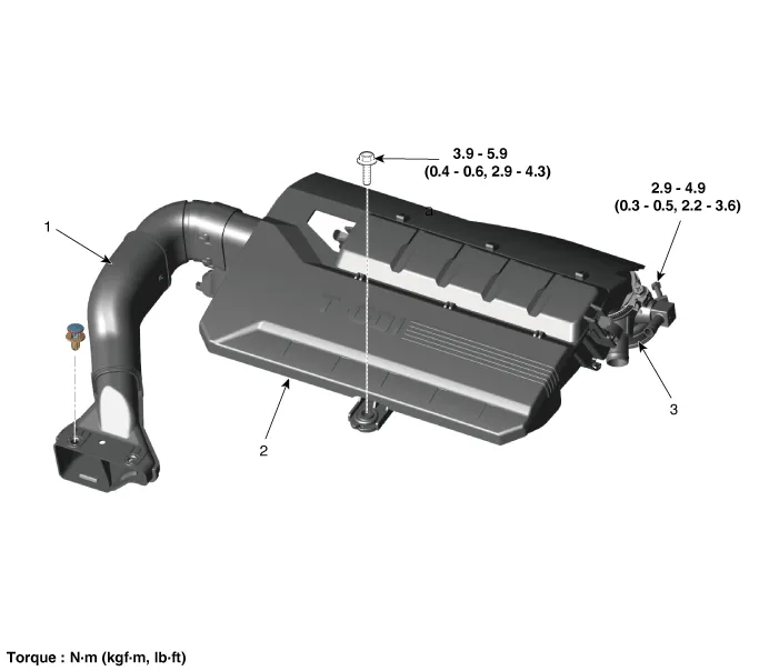
| 1. Air duct 2. Air cleaner assembly | 3. Air intake hose |
Repair procedures
| Removal and Installation |
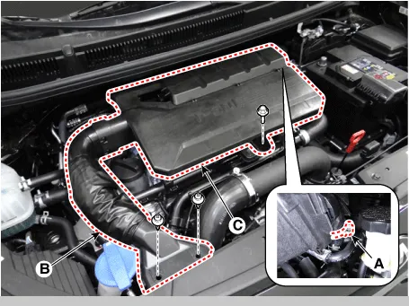
| 1. | Unfasten the air intake hose clamp (A).
|
| 2. | Disconnect the air duct (B), and then remove the air cleaner assembly (C).
|
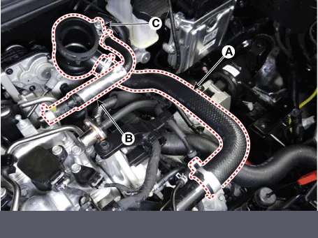
| 3. | Disconnect the recirculation valve (RCV) hose (A) and breather hose (B). |
| 4. | Disconnect the air intake hose (C).
|
| 5. | Installation is reverse order of removal. |
| 1. | Open the air cleaner element cover (A) by unlocking the clamp.
|
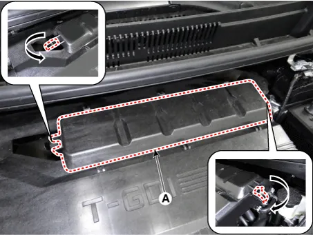
| 2. | Unlock the air cleaner element camshaft (A) by turning in the direction of arrow.
|
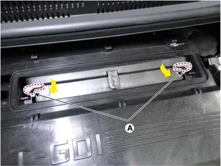
| 3. | Replace the air cleaner element (A) with a new one.
|
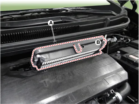

| 4. | Close the service cover by hooking the clamp. |
| Inspection |
| 1. | Remove the air cleaner element. |
| 2. | Check if the air filter is excessively dirty. If so, replace the air cleaner element. |
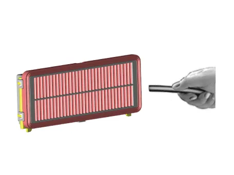
| 3. | If the air cleaner element needs to be cleaned, blow compressed air as shown in the illustration to clean it.
|

| 4. | Reinstall the air cleaner element. |
Components and components location Components 1. Manifold absolute pressure sensor (MAPS) 2. Intake manifold 3. Electronic throttle body control (ETC) module gasket 4.
Other information:
Kia Picanto (JA) 2017-2026 Service & Repair Manual: Lighting System
Specifications Specification Item Type Bulb Watt (W) Front Headlamp Halogen (Position lamp) Low/High H4 LL 55/60 Turn signal lamp PY21WLL 21 Position lamp W5WLL 5 Halogen (Position lamp + DRL) Low/High HB3 (9005HL+) 60 Turn signal lamp LED LED Po
Kia Picanto (JA) 2017-2026 Service & Repair Manual: License Lamps
Repair procedures Removal 1. Disconnect the negative (-) battery terminal. 2. Remove the license lamp assembly (A) after pressing the locking pin. 3. Disconnect the license lamp connector (A). 4. Remove the license lamp bulb (B) after removing the license lamp socket (A).
Categories
- Manuals Home
- Kia Picanto Owners Manual
- Kia Picanto Service Manual
- Cylinder Head
- Front Disc Brake
- Engine Mechanical System
- New on site
- Most important about car
