Kia Picanto (JA): Intake And Exhaust System / Intake Manifold
Components and components location
| Components |

| 1. Manifold absolute pressure sensor (MAPS) 2. Intake manifold 3. Electronic throttle body control (ETC) module gasket | 4. Intake manifold gasket 5. Positive crankcase ventilation (PCV) hose 6. Vacuum hose & pipe |
Repair procedures
| Removal and Installation |
| 1. | Disconnect the negative battery terminal. |
| 2. | Remove the air cleaner assembly.
(Refer to Intake and Exhaust System - "Air Cleaner")
|
| 3. | Disconnect the wiring connectors and harness clamps and remove the connector brackets around the intake manifold.
|

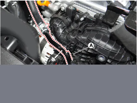
| 4. | Separate the recirculation valve (RCV) pipe (A).
|

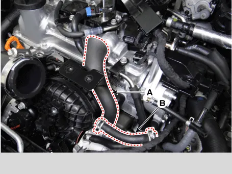
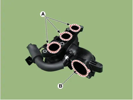
| 5. | Disconnect the positive crankcase ventilation (PCV) hose (A) and vacuum hose (B).
|
| 6. | Separate the water return pipe (A) from the intake manifold.
|
| 7. | Unfasten the electronic throttle body control (ETC) module bolts.
(Refer to Engine Control / Fuel System - "ETC (Electronic throttle body control) System")
|
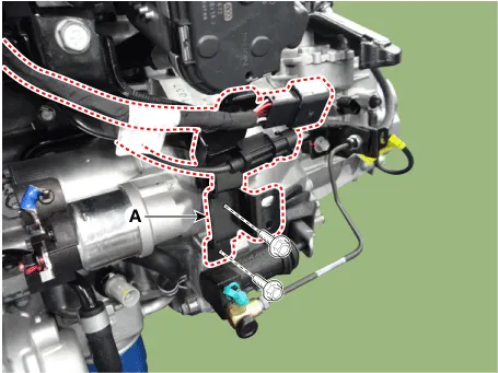
| 8. | Remove the connector bracket (A).
|
| 9. | Remove the intake manifold stay (A).
|

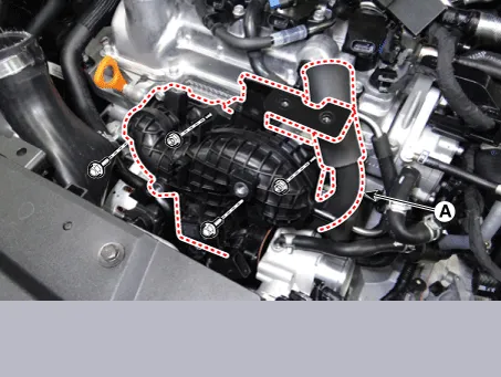
| 10. | Remove the intake manifold (A).
|
| 11. | Install in the reverse order of removal.
|


Components and components location Components 1. Air duct 2. Air cleaner assembly 3. Air intake hose Repair procedures Removal and Installation Air Cleaner Assembly 1.
Components and components location Components 1. Coupler heat protector 2. Warm-up catalytic converter (WCC) 3. Warm-up catalytic converter (WCC) gasket 4.
Other information:
Kia Picanto (JA) 2017-2026 Service & Repair Manual: Back View Camera System
Components and components location Component Location 1. Back view camera 2. AVN head unit 3. steering angle sensor Description and operation Description 1. To display back of the vehicle to assist the driver, it receives vehicle rearside image signal from the rearview camera and displays it on AVN head unit monitor
Kia Picanto (JA) 2017-2026 Service & Repair Manual: Rear Wiper/Washer
C
Categories
- Manuals Home
- Kia Picanto Owners Manual
- Kia Picanto Service Manual
- Suspension System
- Battery
- Coolant
- New on site
- Most important about car

Copyright © 2026 www.kpicanto.com - 0.0184