Kia Picanto (JA): Heater / Heater Core
Repair procedures
| Replacement |
| 1. | Disconnect the negative (-) battery terminal. |
| 2. | Remove the heater unit.
(Refer to Heater - "Heater Unit")
|
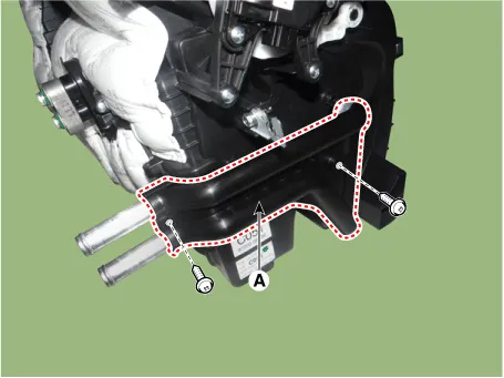
| 3. | Remove the heater core cover (A) after loosening the mounting screws.
|
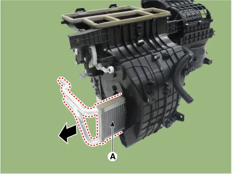
| 4. | Pull out the heater core (A) from the heater unit.
|
| 5. | Install in the reverse order of removal.
|

Components and components location Component Location 1. Mode Control Actuator Description and operation Description The mode control actuator is located at the heater unit.
Repair procedures Replacement 1.Disconnect the negative (-) battery terminal. 2.Remove the heater unit. (Refer to Heater - "Heater Unit") 3.
Other information:
Kia Picanto (JA) 2017-2026 Service & Repair Manual: Emergency Call (eCall) Button
Components and components location Component Repair procedures Removal 1. Disconnect the negative (-) battery terminal. 2. Using a screwdriver or remover, separate the map lamp lens (A) from the map lamp. 3. Remove the map lamp (A) after loosening the screws.
Kia Picanto (JA) 2017-2026 Service & Repair Manual: Power Windows
Components and components location Component Location 1. Driver power window switch 2. Assist power window switch 3. Rear power window switch 4. Front window motor 5. Rear window motor Description and operation Safety Function of Power Window When driver door power window auto-up switch is operated, safety function is acti
Categories
- Manuals Home
- Kia Picanto Owners Manual
- Kia Picanto Service Manual
- Timing Chain
- Immobilizer System
- Automatic Transaxle Fluid
- New on site
- Most important about car
