Kia Picanto (JA): Seat Electrical / Seat Heater Switch
Components and components location
| Components |
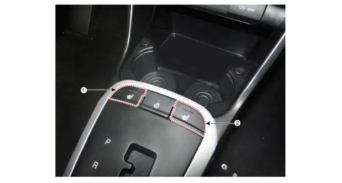
| 1. Driver side seat heater switch | 2. Passenger side seat heater switch |
Schematic diagrams
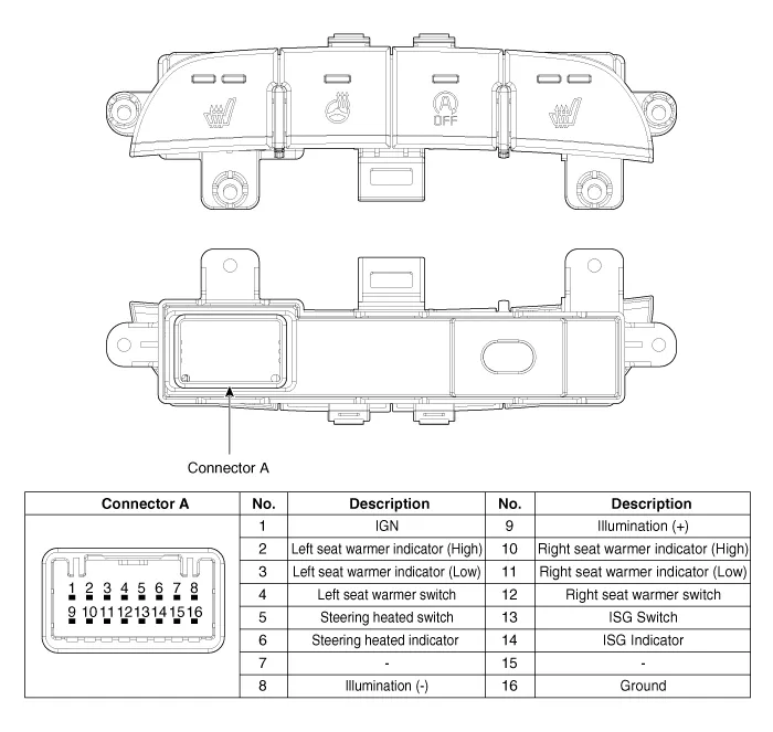
| Circuit Diagram |
Repair procedures
| Removal |
| 1. | Disconnect the negative (-) battery terminal. |
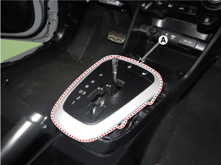
| 2. | To remove the gear knob & gear boots (A) pull both of it up.
|

| 3. | Using a remover, remove the console indicator cover assembly (A).
|
| 4. | Disconnect the connector (A) from the console indicator cover assembly.
|

| 5. | Remove the console upper cover switch (A) after loosening the mounting screws.
|

| Installation |
| 1. | Install the console upper cover switch. |
| 2. | Connect the console indicator cover assembly connector. |
| 3. | Install the console indicator cover assembly. |
| 4. | Install the gear knob & gear boots. |
| 5. | Connect the negative (-) battery terminal. |
Components and components location Component Location 1. Seat heater unit 2. Front seat back heater 3. Front seat cushion heater Schematic diagrams Circuit Diagram Repair procedures Inspection 1.
Specifications Specifications Smart Key Unit Items Specification Rated voltage DC 12 V Operating voltage DC 9 - 16 V Operating temperature -31 - 167°F (-35 - 75°C) Load Max.
Other information:
Kia Picanto (JA) 2017-2026 Service & Repair Manual: Headlamp Leveling Switch
Schematic diagrams Circuit Diagram Repair procedures Removal 1.Disconnect the negative (-) battery terminal. 2.Remove the crash pad lower panel. (Refer to Body - "Crash Pad Lower Panel") 3.Remove the crash pad side switch (A) after loosening the mounting screws.
Kia Picanto (JA) 2017-2026 Service & Repair Manual: Indicators And Gauges
Troubleshooting Troubleshooting Error Item Failure symptom Inspection items Detailed inspections Relevant Parts/ Components Screen display LCD scree
Categories
- Manuals Home
- Kia Picanto Owners Manual
- Kia Picanto Service Manual
- Body Electrical System
- Cooling System
- Normal Condition
- New on site
- Most important about car
