Kia Picanto (JA): Blower / Power Mosfet
Repair procedures
| Inspection |
| 1. | Ignition "ON" |
| 2. | Manually operate the control switch and measure the voltage of blower motor. |
| 3. | Select the control switch to raise voltage until high speed.
|

| Replacement |
| 1. | Disconnect the negative (-) battery terminal. |
| 2. | Remove the glove box housing.
(Refer to Body - "Glove Box Housing")
|
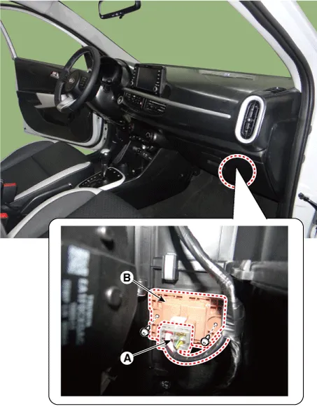
| 3. | Disconnect the connector (A) and then remove the power mosfet (B) after loosening the mounting screws.
|
| 4. | Install in the reverse order of removal. |
Repair procedures Inspection 1.Measure terminal - to - terminal resistance of blower resistor. 2.measured resistance is not within specification, the blower resistor must be replaced.
Description and operation Description This has particle filter which eliminates foreign materials and odor. The particle filter includes odor filter as well as conventional dust filter to ensure comfortable interior environment.
Other information:
Kia Picanto (JA) 2017-2026 Service & Repair Manual: Junction Box (Engine Compartment)
Components and components location Component Location E/R Junction Box Circuit (E/R Junction Block) E/R Junction Box Circuit (E/R Junction Block) Repair procedures Inspection 1. Disconnect the negative (-) battery terminal.
Kia Picanto (JA) 2017-2026 Service & Repair Manual: Sunroof Motor
Repair procedures Inspection 1.Disconnect the negative (-) battery terminal. 2.Remove the roof trim assembly. (Refer to Body - "Roof Trim Assembly") 3.Remove the glass motor (A) after loosening the mounting screws. 4.
Categories
- Manuals Home
- Kia Picanto Owners Manual
- Kia Picanto Service Manual
- Timing Chain
- Heating,Ventilation, Air Conditioning
- Automatic Transaxle Fluid
- New on site
- Most important about car
