Kia Picanto (JA): Lubrication System / Oil Level Gauge & Pipe
Repair procedures
| Removal and Installation |
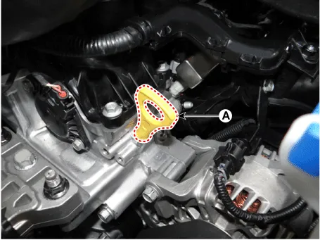
| 1. | Remove the oil level gauge (A).
|
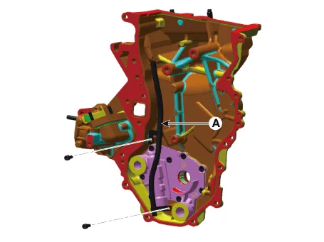
| 2. | Remove the timing chain cover & oil pump assembly.
(Refer to Timing System - "Timing Chain Cover & Oil Pump Assembly")
|
| 3. | Remove the oil level gauge guide (A).
|
| 4. | Install in the reverse order of removal. |
Repair procedures Removal 1.Remove the engine room under cover. (Refer to Engine and Transaxle Assembly - “Engine Room Under Cover”) 2.
Repair procedures Removal and Installation Do not disassemble the oil pump (A) from timing chain cover & oil pump assembly because it is supplied as timing chain cover & oil pump assembly & oil pump assembly.
Other information:
Kia Picanto (JA) 2017-2026 Service & Repair Manual: License Lamps
Repair procedures Removal 1. Disconnect the negative (-) battery terminal. 2. Remove the license lamp assembly (A) after pressing the locking pin. 3. Disconnect the license lamp connector (A). 4. Remove the license lamp bulb (B) after removing the license lamp socket (A).
Kia Picanto (JA) 2017-2026 Service & Repair Manual: Blower Unit
Components and components location Component Location 1. Blower Unit Components 1. Intake Actuator 2. Intake Case [Lower] 3. Air Filter 4. FET 5. Resister 6. Intake Seal 7. Intake Case [Upper] 8. Intake Door Assembly 9. Anti Noise Pad 10.
Categories
- Manuals Home
- Kia Picanto Owners Manual
- Kia Picanto Service Manual
- Cooling System
- Body Electrical System
- Thermostat
- New on site
- Most important about car
