Kia Picanto (JA): Brake System / Rear Disc Brake
Components and components location
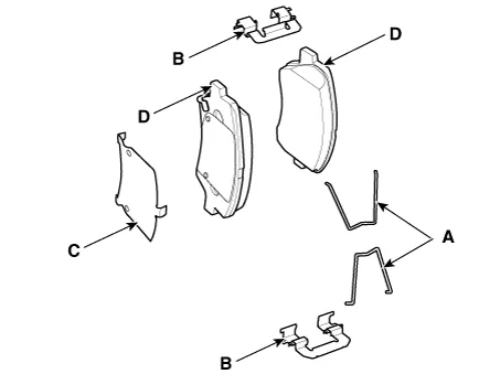
| Components |
| 1. Return spring 2. Brake pad assembly [OUT] 3. Brake pad assembly [IN] 4. Pad liner | 5. Brake member 6. Caliper body 7. Cable guide |
Repair procedures
| Removal |
| 1. | Remove the wheel tire (A).
|

| 2. | Disconnect the parking brake calbe pin.
|

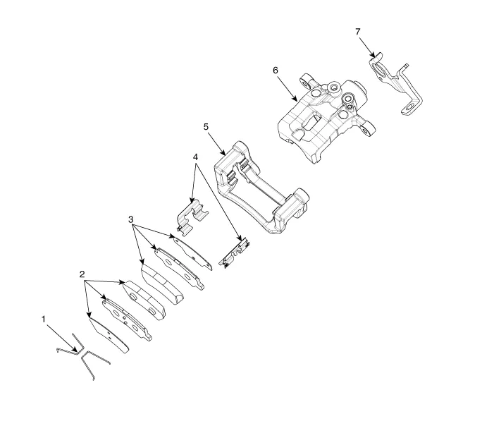
| 3. | Remove the brake lever spring and then loosening the nut.
|
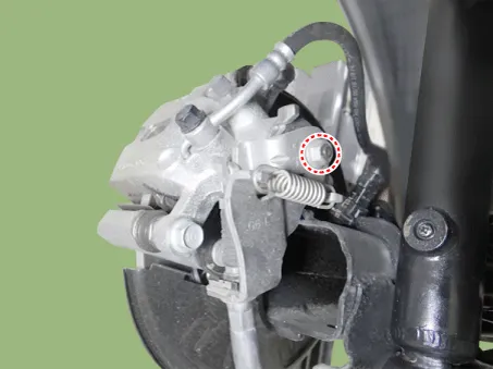
| 4. | Disconnect the parking brake cable.
|
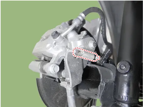
| 5. | Loosen the bolt and then removing the brake lever bracket.
|
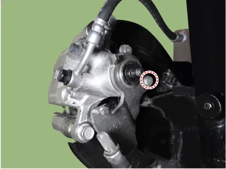
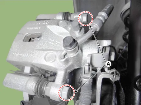
| 6. | Loosen the eyebolt (A) and guide bolts (B) and then remove the caliper body.
|
| 7. | Remove the return spring and brake pad.
|
| 8. | Loosen the bolt and then remove the caliper member.
|
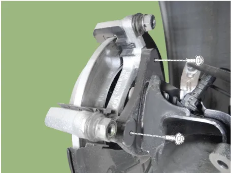
| 9. | Loosen the screw and then remove the brake disc.
|

| 10. | Install in the reverse order of removal. |
| Replacement |
| 1. | Remove the wheel tire (A).
|
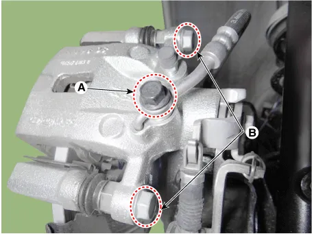
| 2. | Loosen the bolts (A) and then removing the rear caliper body.
|
| 3. | Remove the return spring and brake pad.
|

| Inspection |
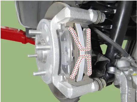
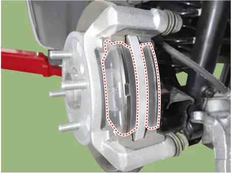
| 1. | Check the brake pads for wear and fade. |
| 2. | Check the brake disc for damage and cracks. |
| 3. | Remove
all rust and contamination from the surface, and measure the disc
thickness at 8 points, at least, at the same distance apart (5mm) from
the brake disc outer circle.
|

| 4. | If wear exceeds the limit, swab left and right discs and pad assemblies of the vehicle. |
| 1. | Check the pad wear. Measure the pad thickness and replace it, if it is less than the specified value.
|
| 2. | Check that grease is applied to sliding contact points and check the pad and backing metal for damage. |
| 1. | Place a dial gauge about 5mm (0.2 in.) from the outer circumference of the brake disc, and measure the runout of the disc.
|
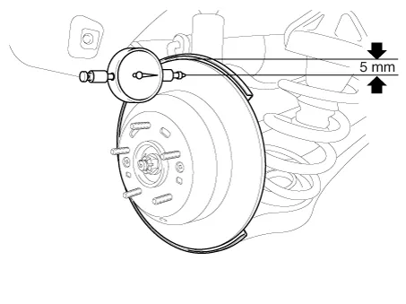
| 2. | If the runout of the brake disc exceeds the limit specification, replace the disc, and then measure the runout again. |
| 3. | If
the runout does not exceed the limit specification, install the brake
disc after turning it 180° and then check the brake disc again for
runout. |
| 4. | If the runout cannot be corrected by changing the position of the brake disc, replace the brake disc. |
| Installation |
| 1. | Install in the reverse order of removal. |
| 2. | Rotate the caliper piston and push the direction of the arrow.
|

| 3. | After installation, bleed the brake system.
(Refer to Brake system - "Brake System")
|
Components and components location Components 1. Guid bolt 2. Caliper body 3. Caliper member 4. Pad liner 5. Brake pad assembly [OUT] 6. Brake pad assembly [IN] 7.
Components and components location Components 1. Shoe hold down pin 2. Shoe adjuster 3. Upper return spring 4. Adjusting lever 5. Shoe 6. Adjusting spring 7.
Other information:
Kia Picanto (JA) 2017-2026 Service & Repair Manual: Power Door Mirror Actuator
Components and components location Components 1. Side repeater lamp Repair procedures Inspection 1. Disconnect the negative (-) battery terminal. 2. Remove the front door quadrant inner cover (A). 3. Disconnect the tweeter speaker connector (A).
Kia Picanto (JA) 2017-2026 Service & Repair Manual: Smart Key System
Specifications Specifications Smart Key Unit Items Specification Rated voltage DC 12 V Operating voltage DC 9 - 16 V Operating temperature -31 - 167°F (-35 - 75°C) Load Max. 4mA (When welcome light function "OFF") RF Receiver Items
Categories
- Manuals Home
- Kia Picanto Owners Manual
- Kia Picanto Service Manual
- Charging System
- Fuel Delivery System
- Battery
- New on site
- Most important about car
