Kia Picanto (JA): Intake And Exhaust System / Intercooler
Components and components location
| Components |

| 1. Intercooler air guard 2. Intercooler 3. Recirculation valve (RCV) control solenoid valve & vacuum hose 4. Recirculation valve (RCV) 5. Recirculation valve (RCV) hose | 6. Intercooler upper mounting bracket & insulator 7. Intercooler inlet hos & pipe 8. Intercooler outlet hos & pipe 9. Intercooler lower mounting insulator |
Repair procedures
| Removal and Installation |
| 1. | Disconnect the negative battery terminal. |
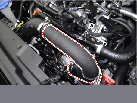
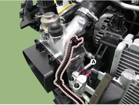
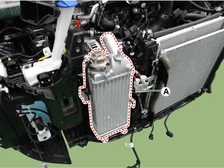
| 2. | Disconnect the intercooler outlet hose & pipe (A)
|
| 3. | Disconnect the recirculation valve (RCV) hose (A) and vacuum hose (B).
|

| 4. | Remove the engine room under cover.
(Refer to Engine and Transaxle Assembly - "Engine Room Under Cover")
|
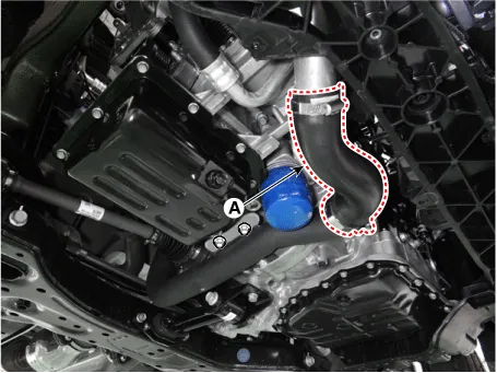
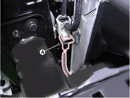
| 5. | Disconnect the intercooler inlet hose (A)
|
| 6. | Remover the front bumper assembly.
(Refer to body (Interior and Exterior) - "Front Bumper Assembly")
|
| 7. | Remove the headlamps.
(Refer to Body Electrical System - "Head Lamps")
|
| 8. | Disconnect the hood latch.
(Refer to Body (Interior and Exterior) - "Hood Latch")
|
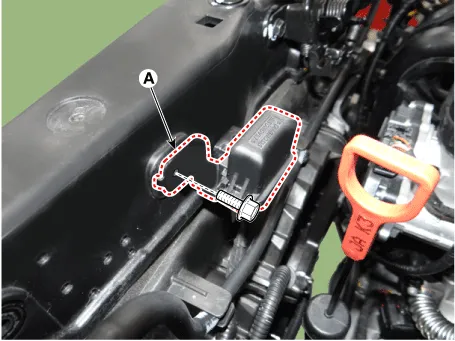
| 9. | Remove the multi-purpose check connector (MPCC) bracket (A).
|
| 10. | Disconnect the reservoir hose clip (A).
|

| 11. | Remove the radiator upper mounting bracket (A).
|

| 12. | Remove the radiator support upper member assembly (A).
|

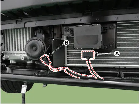
| 13. | Disconnect the assist emergency braking (AEB) unit connector (A) and horn connector (B).
|
| 14. | Remove the front bumper beam (A).
|

| 15. | Disconnect the boost pressure sensor (BPS) connector (A).
|
| 16. | Disconnect the solenoid valve connector (A).
|
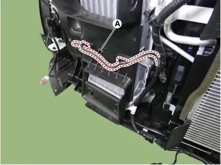
| 17. | Remove the wiring (A) from the intercooler air guard.
|
| 18. | Remove the intercooler air guard (A).
|
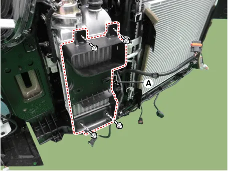
| 19. | Remove the intercooler (A).
|
| 20. | Install in the reverse order of removal. |
Components and components location Components 1. Coupler heat protector 2. Warm-up catalytic converter (WCC) 3. Warm-up catalytic converter (WCC) gasket 4.
Components and components location Components 1. Front muffler 2. Catalytic converter & Center muffler assembly 3. Rear muffler 4. Rubber hanger 5.
Other information:
Kia Picanto (JA) 2017-2026 Service & Repair Manual: Map Lamp
Repair procedures Removal • Put on gloves to prevent hand injuries. • When removing with a flat-tip screwdriver or remover, wrap protective tape around the tools to prevent damage to components.
Kia Picanto (JA) 2017-2026 Service & Repair Manual: Rear Wiper/Washer
C
Categories
- Manuals Home
- Kia Picanto Owners Manual
- Kia Picanto Service Manual
- Charging System
- Battery
- Brake System
- New on site
- Most important about car

Copyright © 2026 www.kpicanto.com - 0.0219