Kia Picanto (JA): Body Electrical System / Back View Camera System
Components and components location
| Component Location |
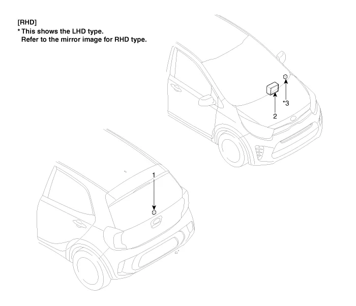
| 1. Back view camera 2. AVN head unit | 3. steering angle sensor |
Description and operation
| Description |
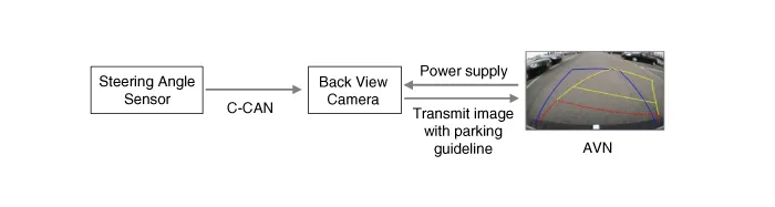
| 1. | To
display back of the vehicle to assist the driver, it receives vehicle
rearside image signal from the rearview camera and displays it on AVN
head unit monitor or LHS of inside rearview mirror. |
| 2. | Back
view camera is a supplementary device that displays dead zone on
monitor screen that automatically operates when the gear stays in "R"
for over 3 seconds. |
| 3. | It
displays the estimated trajectory with parking guideline in accordance
with the operating angle of steering wheel. (There is no separate unit.)
|
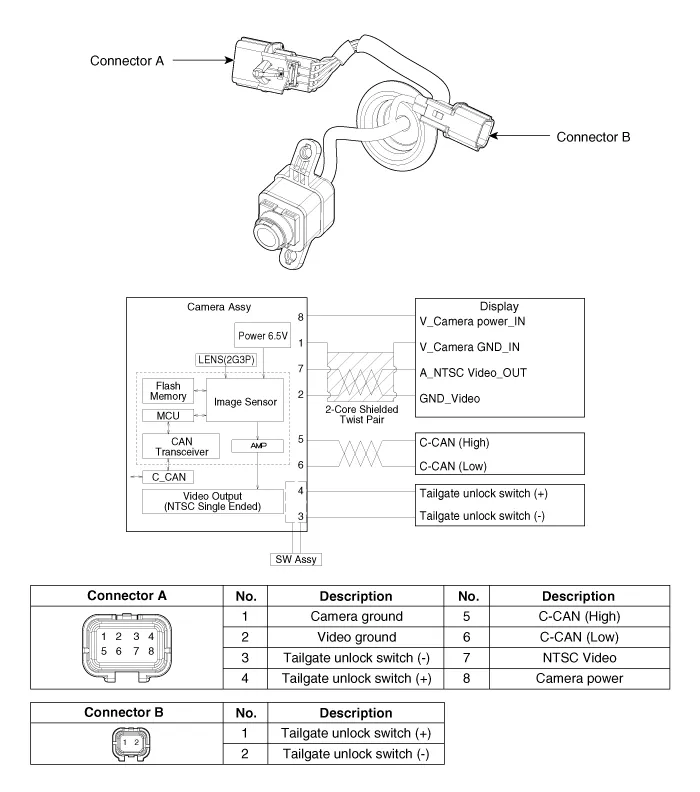
Schematic diagrams
| Circuit Diagram |
Repair procedures
| Removal |
In case of bad quality or poor focus, be sure to check the camera lense surface condition and foreign materials. |

| 1. | Disconnect the negative (-) battery terminal. |
| 2. | Remove the tailgate trim.
(Refer to Body - "Tailgate Trim")
|
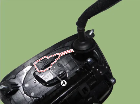
| 3. | Disconnect the tailgate outside handle assembly connector (A).
|
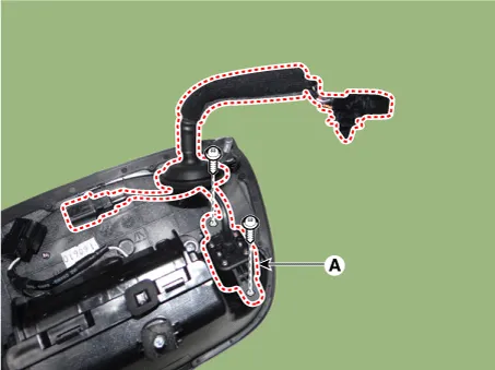
| 4. | Remove the tailgate outside handle assembly (A) after loosening the mounting nuts.
|
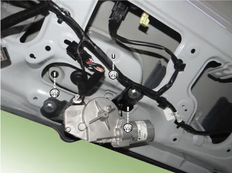

| 5. | Disconnect the tailgate open switch connector (A).
|
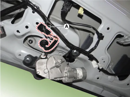
| 6. | Remove the back view camera assembly (A) after loosening the mounting screws.
|
| Installation |
| 1. | Install the back view camera assembly. |
| 2. | Connect the tailgate open switch connector. |
| 3. | Install the tailgate outside handle assembly. |
| 4. | Connect the tailgate outside handle assembly connector. |
| 5. | Install the tailgate trim. |
| 6. | Connect the negative (-) battery terminal. |
Repair procedures Inspection 1.Disconnect the negative (-) battery terminal. 2.Remove the roof trim assembly. (Refer to Body - "Roof Trim Assembly") 3.
Specifications Specifications [BCM Type] Items Specifications Rated voltage DC 12 V Operating voltage DC 9 - 16 V Operating temperature -31 - 167°F (-35 - 75°C) Dark current SMK : 3mA / Keyless : 3.
Other information:
Kia Picanto (JA) 2017-2026 Service & Repair Manual: High Mounted Stop Lamp
Repair procedures Removal 1. Disconnect the negative (-) battery terminal. 2. Open the tailgate. 3. Loosen the high mounted stop lamp mounting nuts (A). 4. Disconnect the washer nozzle (A) and high mounted stop lamp connector (B). 5. Remove the high mounted stop lamp (C).
Kia Picanto (JA) 2017-2026 Service & Repair Manual: Rear Wiper Motor
Repair procedures Inspection Rear Wiper Motor 1.Remove the connector from the rear wiper motor. 2.Connect positive (+) battery cables to terminal 1 and negative (-) battery cables to terminal 2 respectively. 3.Check that the motor operates normally.
Categories
- Manuals Home
- Kia Picanto Owners Manual
- Kia Picanto Service Manual
- Battery
- Engine Control / Fuel System
- Front Disc Brake
- New on site
- Most important about car
