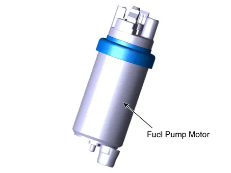
Kia Picanto (JA): Fuel Delivery System / Fuel Pump Motor
Repair procedures
| Removal |
| 1. | Remove the fuel pump.
(Refer to Fuel Delivery System - "Fuel Pump")
|
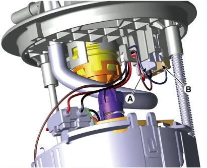
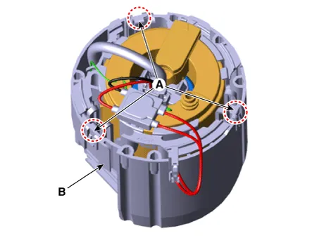
| 2. | Disconnect the fuel pump motor connector (A) and fuel sender connector (B).
|
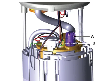
| 3. | Disconnect the fuel feed tube quick-connector (A) after removing the fixing clip (B).
|
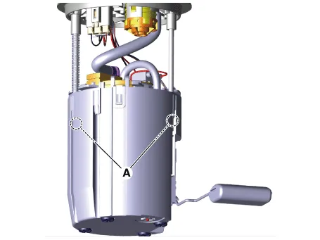
| 4. | Remove the cushion pipe fixing clip (A), and then separate the head assembly (B) from reservoir cup.
|
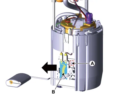
| 5. | Press the fixing hook (A) with a driver and then remove fuel sender in the arrow direction.
|
| 6. | Remove the reservoir-cup (B) after releasing the fixing hooks (A).
|
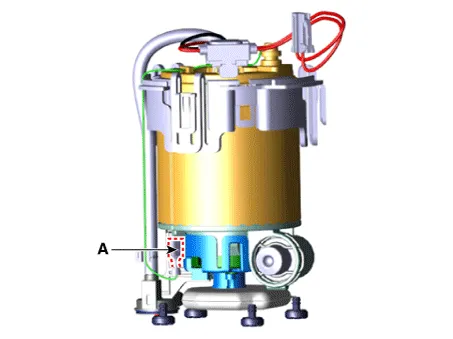
| 7. | Disconnect the ground pin (A).
|
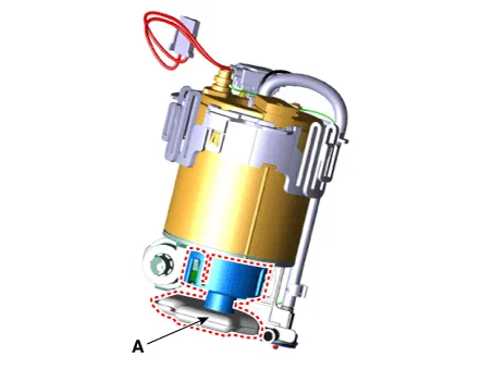
| 8. | Remove the fixing clip (A), and then assist pump assembly (B).
|

| 9. | Remove the free-filter (A) after releasing the fixing hooks.
|
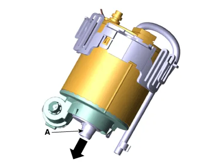
| 10. | Separate the electric pump motor (A).
|
Repair procedures Removal 1.Remove the fuel pump. (Refer to Fuel Delivery System - "Fuel Pump") 2.Disconnect the fuel sender connector (A).
Repair procedures Removal 1.Remove the fuel pump. (Refer to Fuel Delivery System - "Fuel Pump") 2.Disconnect the fuel pump motor connector (A) and fuel sender connector (B).
Other information:
Kia Picanto (JA) 2017-2026 Service & Repair Manual: Multifunction Switch
Specifications Specifications Items Specifications Rated voltage DC 12 V Operating temperature range -22 - 176°F (-30 - 80°C) Rated load Washer Washer : 6A (Motor load) Components and components location Component 1 .
Kia Picanto (JA) 2017-2026 Service & Repair Manual: Heater Unit
Components and components location Component Location 1. Heater Unit Components [LH] 1. Heater Core Cover 2. Mode Control Actuator 3. Mode Control Actuator braket 4. Mode Cam 5. Mode Cam 6. Heater Core 7. Door Cover [Floor] 8. Heater Case [LH] [RH] 1.
Categories
- Manuals Home
- Kia Picanto Owners Manual
- Kia Picanto Service Manual
- Front Disc Brake
- Engine Control / Fuel System
- Engine Mechanical System
- New on site
- Most important about car
