Kia Picanto (JA): Fuses / Engine compartment fuse replacement
1. Turn the ignition switch and all other switches off.
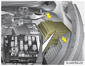
2. Remove the fuse panel cover by pressing the tab and pulling the cover up. When the blade type fuse is disconnected, remove it by using the clip designed for changing fuses located in the engine room fuse box. Upon removal, securely insert reserve fuse of equal quantity.
3. Check the removed fuse; replace it if it is blown. To remove or insert the fuse, use the fuse puller in the engine compartment fuse panel.
4. Push in a new fuse of the same rating, and make sure it fits tightly in the clips. If it fits loosely, consult a professional workshop. Kia recommends to consult an authorized Kia dealer/service partner.
CAUTION
After checking the fuse panel in the engine compartment, securely install the fuse panel cover through the audible clicking sound. If not, electrical failures may occur from water contact.
Multi fuse
NOTICE
If the multi fuse is blown, consult a professional workshop. Kia recommends to consult an authorized Kia dealer/service partner.
CAUTION
Do not remove fuses, relays and terminals fastened with bolts or nuts. The fuses, relays and terminals may be fastened incompletely, and it may cause a possible fire. If fuses, relays and terminals fastened with bolts or nuts are blown, consult a professional workshop. Kia recommends to consult an authorized Kia dealer/service partner.
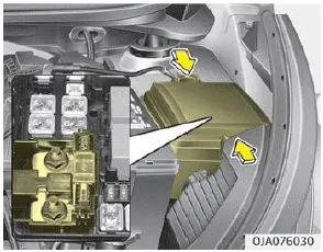
1. Turn the ignition switch and all other switches off. 2. Open the fuse panel cover. 3. Pull the suspected fuse straight out. Use the removal tool provided in the main fuse box in the engine compartment.
Inside the fuse/relay panel covers, you can find the fuse/relay label describing fuse/relay name and capacity. NOTICE Not all fuse panel descriptions in this manual may be applicable to your vehicle.
Other information:
Kia Picanto (JA) 2017-2026 Service & Repair Manual: ESCL(Electronic Steering Column Lock)
Components and components location Component Repair procedures Removal 1.Disconnect the negative(-) battery terminal. 2.Remove the crash pad lower panel. (Refer to Body - "Crash Pad Lower Panel") 3.Remove the steering column upper and lower shrouds.
Kia Picanto (JA) 2017-2026 Service & Repair Manual: Blower Unit
Components and components location Component Location 1. Blower Unit Components 1. Intake Actuator 2. Intake Case [Lower] 3. Air Filter 4. FET 5. Resister 6. Intake Seal 7. Intake Case [Upper] 8. Intake Door Assembly 9. Anti Noise Pad 10.
Categories
- Manuals Home
- Kia Picanto Owners Manual
- Kia Picanto Service Manual
- Heating,Ventilation, Air Conditioning
- Cylinder Head
- Body Electrical System
- New on site
- Most important about car
