Kia Picanto (JA): Power Door Locks / Power Door Lock Module
Components and components location
| Components |

| 1. Door lock/unlock knob cable 2. Door inside handle cable | 3. Door latch assembly |
Repair procedures
| Inspection |
|

| 1. | Remove the front door trim.
(Refer to Body - "Front Door Trim")
|
| 2. | Remove the front door trim seal.
(Refer to Body - "Front Door Window Glass")
|
| 3. | Disconnect the connector from the actuator.
|

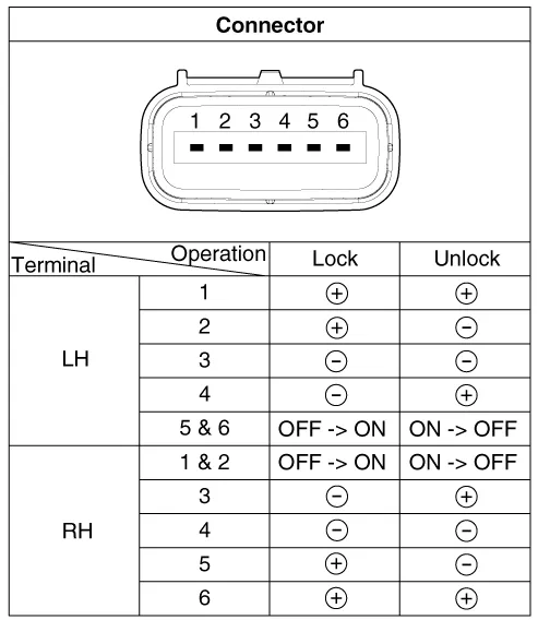
| 4. | Check
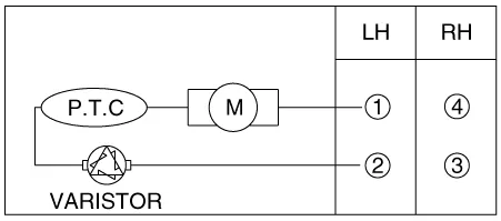
actuator operation by connecting power and ground as shown below. To
prevent damage to the actuator, apply battery voltage only momentarily. [Connector 6 pin Type]
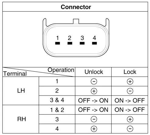
[Connector 4 pin Type]
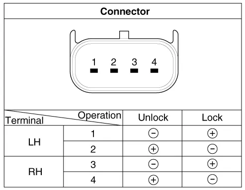
[Connector 2 pin Type]
|


| 1. | Remove the rear door trim.
(Refer to Body - "Rear Door Trim")
|
| 2. | Remove the rear door trim seal.
(Refer to Body - "Rear Door Window Glass")
|
| 3. | Disconnect the connector from the actuator.
|

| 4. | Check
actuator operation by connecting power and ground as shown below. To
prevent damage to the actuator, apply battery voltage only momentarily. [Connector 4 pin Type]
[Connector 2 pin Type]
|
| 1. | Remove the tailgate trim.
(Refer to Body - "Tailgate Trim")
|
| 2. | Disconnect the connectors from the actuator.
|
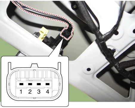
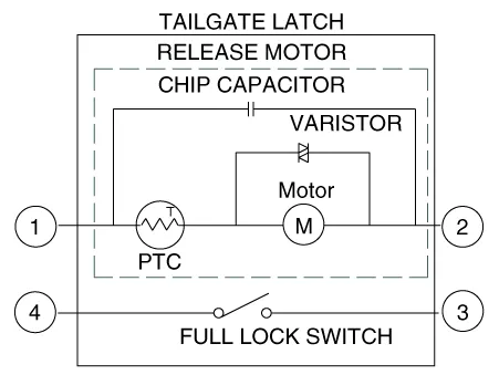
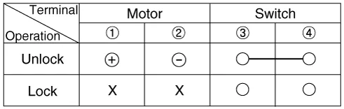
| 3. | Check
actuator operation by connecting power and ground as shown below. To
prevent damage to the actuator, apply battery voltage only momentarily.
|
| 4. | Checking the tailgate of the vehicle power option power refers to the tailgate module. |
Components and components location Component Location 1. Driver power window switch 2. Assist power window switch 3 . Body Comtrol Module (BCM) 4 .
Repair procedures Inspection 1.Check for continuity between the terminals. If there is an abnormality, replace the switch. Removal • When removing with a flat-tip screwdriver or remover, wrap protective tape around the tools to prevent damage to components.
Other information:
Kia Picanto (JA) 2017-2026 Service & Repair Manual: Multifunction Switch
Specifications Specifications Items Specifications Rated voltage DC 12 V Operating temperature range -22 - 176°F (-30 - 80°C) Rated load Washer Washer : 6A (Motor load) Components and components location Component 1 .
Kia Picanto (JA) 2017-2026 Service & Repair Manual: Rear Parking Assist System
Specifications Specification Item Specification Ultrasonic sensor Voltage rating DC 12V Detecting range 11.8 - 39.3 in (30 - 100 cm) Operation voltage DC 9 - 16 V Operation current 60mA Max.
Categories
- Manuals Home
- Kia Picanto Owners Manual
- Kia Picanto Service Manual
- Clutch Cable
- Coolant
- Engine Control / Fuel System
- New on site
- Most important about car
