Kia Picanto (JA): ISG (Idle Stop & Go) System / Brake switch
Components and components location
| Components |
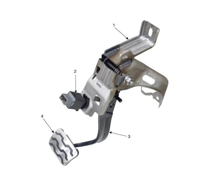
| 1. Brake member assembly 2. Stop lamp switch | 3. Brake pedal arm assembly 4. Brake pedal pad |
Troubleshooting
| Troubleshooting |
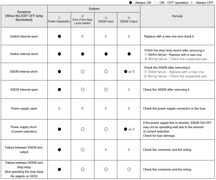
| 1. | Part diagnosis
|
| 2. | Symptom diagnosis
|
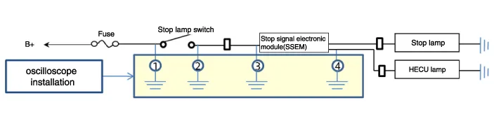
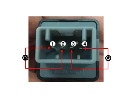
| 3. | Stop lamp switch system diagnosis
SSEM : Stop Signal Electronic Module |
| 4. | Refer to DTC guide when the related DTC codes are displayed. |
Repair procedures
| Removal |
| 1. | Switch "OFF" ignition and disconnect the negative (-) battery terminal. |
| 2. | Remove the crash pad lower panel.
(Refer to Body - "Crash Pad Lower Panel")
|
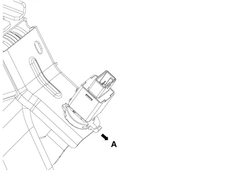
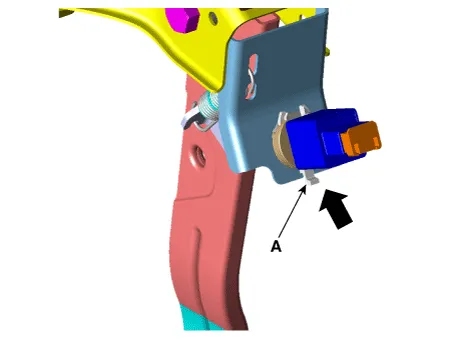
| 3. | Disconnect the stop lamp switch connector (A).
|

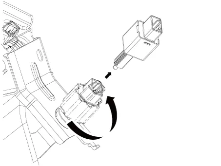
| 4. | Pull the locking plate (A) as indicated by the
|
| 5. | Turn brake switch 45° counterclockwise and remove it.
|
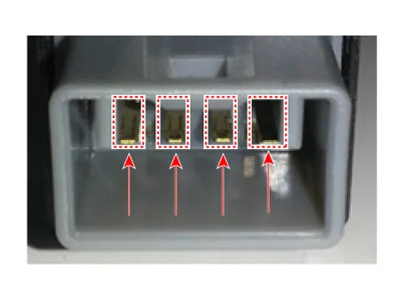
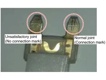
| 6. | Inspect the removed stop lamp switch according to the below procedures.
|
| Installation |
| 1. | Fix the brake pedal arm and insert the brake switch fully until the contact part is invisible.
|

| 2. | After inserting, turn the brake switch 45° clockwise, and then assemble locking plate by pushing it.
|
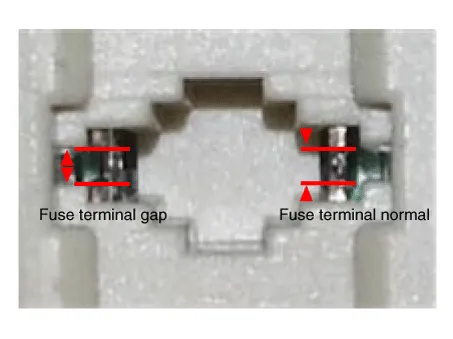
| 3. | Check the gap (A) between brake switch and bracket.
|


| 4. | Install the brake switch connector (A).
|
| Inspection |
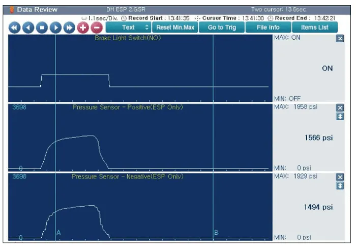
| 1. | Analyze KDS data and confirm if there is anything wrong with the stop lamp switch.
|


Specifications Specification ▷12V, 1.2kW : ISG only Item Specification Rated voltage 12 V, 1.
Description and operation Description Via the seat belt/Door switch, the ISG function can detect that the driver has fastened the seat belt/door.
Other information:
Kia Picanto (JA) 2017-2026 Service & Repair Manual: Rear Glass Defogger Printed Heater
Repair procedures Inspection • Wrap tin foil around the end of the voltmeter test lead to prevent damaging the heater line. Apply pressure on the tin foil with hand and move the tin foil along the grid line to check for open circuits.
Kia Picanto (JA) 2017-2026 Service & Repair Manual: Rear Washer Switch
Repair procedures Inspection Multifunction Switch Inspection 1. Check for continuity between the terminals in each switch position as shown below. Rear Wiper & Washer Switch[LHD] [RHD] Inspection (With KDS/GDS) 1. In the body electrical system, failure can be quickly diagnosed by using the vehicle diagnostic system (KDS/GDS).
Categories
- Manuals Home
- Kia Picanto Owners Manual
- Kia Picanto Service Manual
- Engine Mechanical System
- Cooling System
- Automatic Transaxle Fluid
- New on site
- Most important about car
