Kia Picanto (JA): Tires/Wheels / Alignment
Repair procedures
| Front wheel alignment |
When
using a commercially available computerized wheel alignment equipment
to inspect the front wheel alignment, always position the vehicle on a
level surface with the front wheels facing straight ahead. Prior
to inspection, make sure that the front suspension and steering system
are in normal operating condition and that the tires are inflated to the
specified pressure. |


B - A > 0: Toe in (+) B - A < 0: Toe out (-) |
| 1. | Loosen the tie rod end lock nut. |
| 2. | Remove the bellows clip to prevent the bellows from being twisted. |
| 3. | Adjust
the toe by screwing or unscrewing the tie rod. Toe adjustment should be
made by turning the right and left tie rods by the same amount.
|
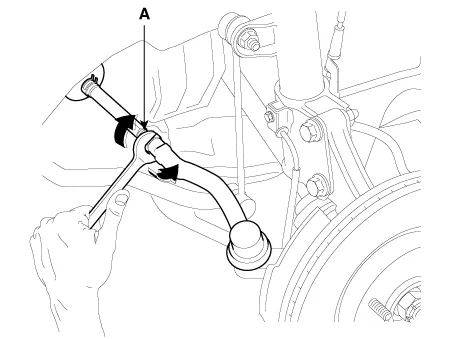
| 4. | When completing the toe adjustment, install the bellows clip and tighten the tie rod end lock nut to specified torque.
|
Europe, Australia
Camber angle : -0.5° ± 0.5°
Caster angle : 4.04° ± 0.5°
General, Middle East, Russia, Europe (High suspension)
Camber angle : -0.33° ± 0.5°
Caster angle : 3.90° ± 0.5°
SX Trim (Export)
Camber angle : -0.24° ± 0.5°
Caster angle : 3.83° ± 0.5° |
| Rear Wheel Alignment |
When
using a commercially available computerized wheel alignment equipment
to inspect the rear wheel alignment, always position the vehicle on a
level surface. Prior to inspection, make sure that the rear
suspension system is in normal operating condition and that the tires
are inflated to the specified pressure. |
B - A > 0: Toe in (+) B - A < 0: Toe out (-) |
Toe:
Europe, Australia
Total : 0.4° (+0.4°/-0.3°)
Individual : 0.15° ± 0.15°
General, Middle East, Russia, Europe (High suspension)
Total : 0.23° ± 0.30°
Individual : 0.11° ± 0.15°
SX Trim (Export)
Total : 0.19° ± 0.30°
Individual : 0.09° ± 0.15° |
Camber: -1.5°±0.5° |
Repair procedures Hub nut tightening sequence Tighten the hub nuts as follows. Tightening torque: 107.9 - 127.5 N·m (11.0 - 13.
Components and components location Components 1. HECU 2. Cluster 3. TPMS SET Switch 4. Wheel speed sensor 5. Tone wheel Description and operation Description Indirect Tire Pressure Monitoring System (TPMS) Using a wheel speed signal from the ESC, the system analyzes the turning radius of the tire and change in tire stiffness to detect a pressure loss.
Other information:
Kia Picanto (JA) 2017-2026 Service & Repair Manual: Keyless Entry And Burglar Alarm
Specifications Specification Item Specification Power source 3 V Operating temperature -22 - 167°F (-30 - 75°C) RF Modulation FSK LF Modulation ASK RF frequency 433.92 MHz Button number 3 Function Door lock Door unlock Tailgate unlock Components and components locat
Kia Picanto (JA) 2017-2026 Service & Repair Manual: Power Door Locks
Components and components location Component Location 1. Driver power window switch 2. Assist power window switch 3 . Body Comtrol Module (BCM) 4 . Door lock knob 5 . Tailgate actuator 6. Door latch lock actuator 7 . Door lock/unlock switch 8 .
Categories
- Manuals Home
- Kia Picanto Owners Manual
- Kia Picanto Service Manual
- Clutch Cable
- Timing Chain
- Normal Condition
- New on site
- Most important about car
