Kia Picanto (JA): Driveshaft and axle / Front Axle Assembly
Components and components location
| Components |
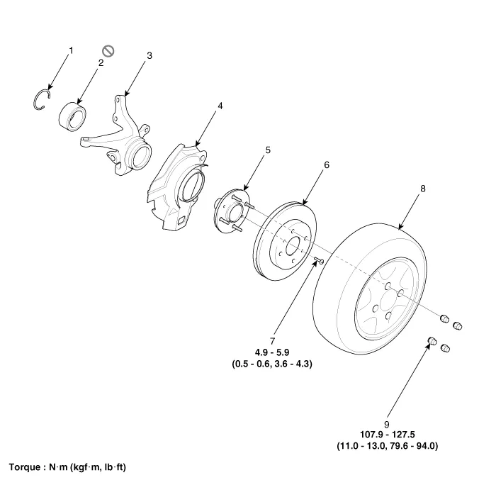
| 1. Snap ring 2. Bearing 3. Axle assembly 4. Brake disc dust cover 5. Wheel hub assembly | 6. Wheel brake disc 7. Brake disc fixing screw 8. Wheel / Tire 9. Wheel nut |
Repair procedures
| Removal |
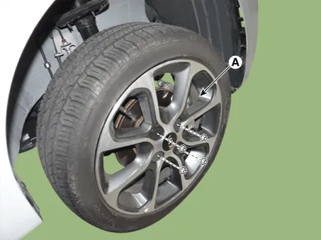
| 1. | Remove the front/rear wheel tire (A).
|

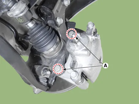
| 2. | Remove the brake caliper mounting bolts (A), and then hold the brake caliper assembly with wire.
|
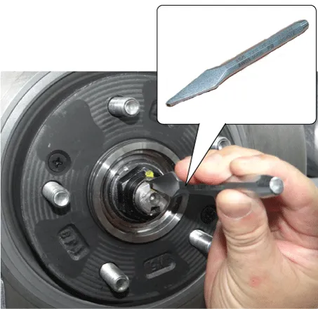
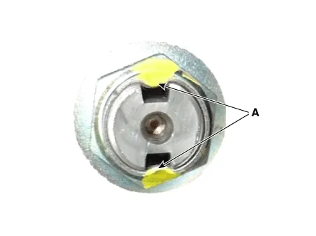
| 3. | By hammering on a chisel, unlock the driveshaft lock hub nut caulking.
|
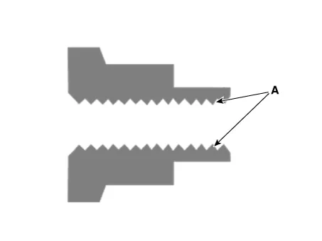
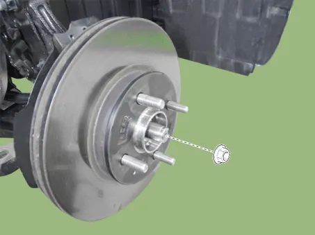
| 4. | Remove the caulking nut from the front axle.
|

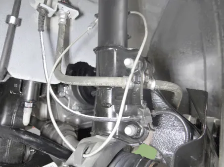
| 5. | Loosen the bolt and then remove the wheel speed sensor.
|

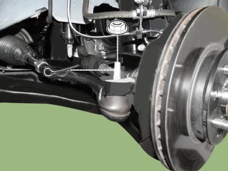
| 6. | Remove the pin and nut from the tie rod end ball joint.
|
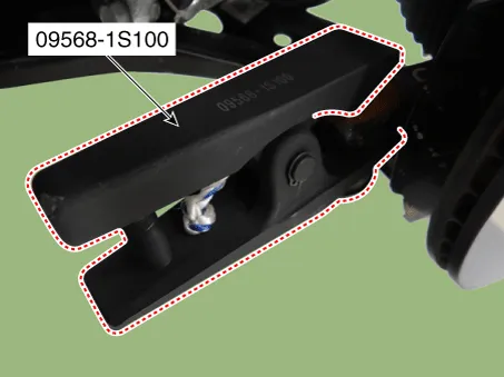
| 7. | Remove the tie rod end ball joint from the knuckle by using the SST (09568-1S100).
|
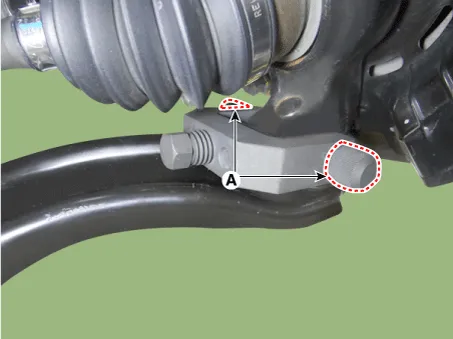
| 8. | Remove the lower arm bolt and nut (A).
|

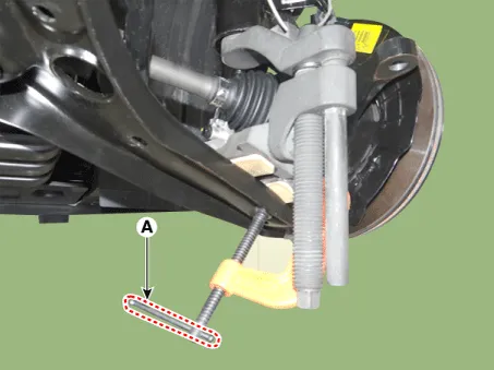
| 9. | Remove the front lower arm from the front knuckle using the SST (0K545-A9100).
|


| 10. | Loosen the screw and then remove the brake disc.
|

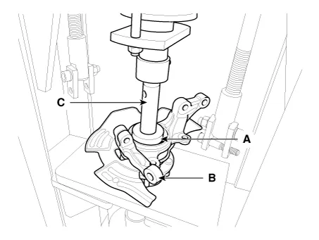
| 11. | Loosen the front strut bolts and nuts and then remove the knuckle assembly (A).
|

| Inspection |
| 1. | Check the hub for cracks and the splines for wear. |
| 2. | Check the brake disc for scoring and damage. |
| 3. | Check the knuckle for cracks |
| 4. | Check the bearing for cracks or damage. |
| Disassembly |
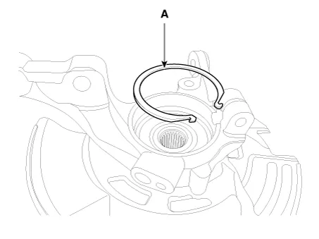
| 1. | Remove the snap ring (A).
|
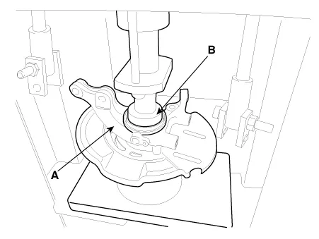
| 2. | Remove the hub assembly from the knuckle assembly.
|
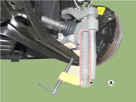
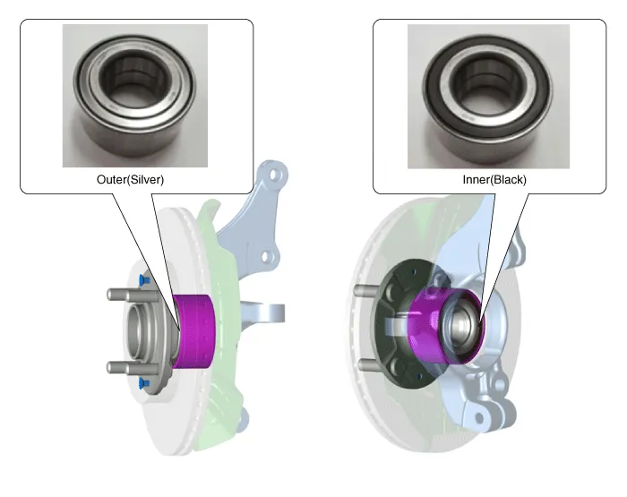
| 3. | Remove the hub bearing inner race from the hub assembly.
|

| 4. | Remove the hub bearing outer race from the knuckle assembly.
|

| 5. | Replace hub bearing with a new one. |
| Reassembly |
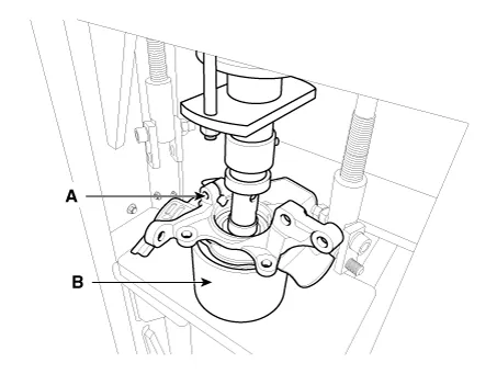
| 1. | Install the hub bearing to the knuckle assembly.
|

| 2. | Install the hub assembly to the knuckle assembly.
|
| 3. | Install the snap ring (A).
|
Specifications Specification Engine T/M Joint type Max.
Other information:
Kia Picanto (JA) 2017-2026 Service & Repair Manual: Power Mosfet
Repair procedures Inspection 1.Ignition "ON" 2.Manually operate the control switch and measure the voltage of blower motor. 3.Select the control switch to raise voltage until high speed. Fan Motor Voltage ManualFirst speed3.
Kia Picanto (JA) 2017-2026 Service & Repair Manual: Climate Control Air Filtar
Description and operation Description This has particle filter which eliminates foreign materials and odor. The particle filter includes odor filter as well as conventional dust filter to ensure comfortable interior environment. Repair procedures Replacement 1.
Categories
- Manuals Home
- Kia Picanto Owners Manual
- Kia Picanto Service Manual
- General Information
- Charging System
- Front Disc Brake
- New on site
- Most important about car
