Kia Picanto (JA): Emergency Call System / Emergency Call (eCall) Button
Kia Picanto (JA) 2017-2026 Service & Repair Manual / Body Electrical System / Emergency Call System / Emergency Call (eCall) Button
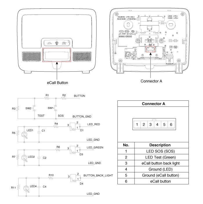
Components and components location
| Component |
Repair procedures
| Removal |
| 1. | Disconnect the negative (-) battery terminal. |
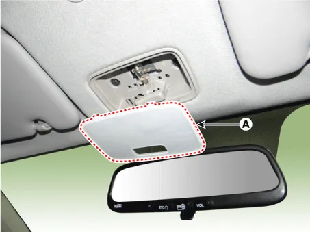
| 2. | Using a screwdriver or remover, separate the map lamp lens (A) from the map lamp.
|
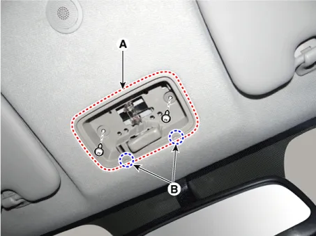
| 3. | Remove the map lamp (A) after loosening the screws.
|

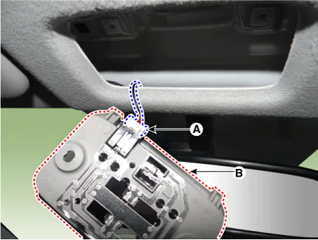
| 4. | Remove the map lamp assembly (B) after disconnecting the map lamp connector (A).
|
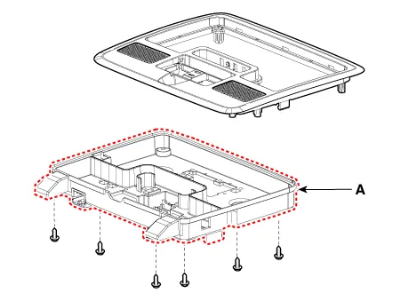
| 5. | Remove the map lamp cover (A) after loosening the mounting screws.
|
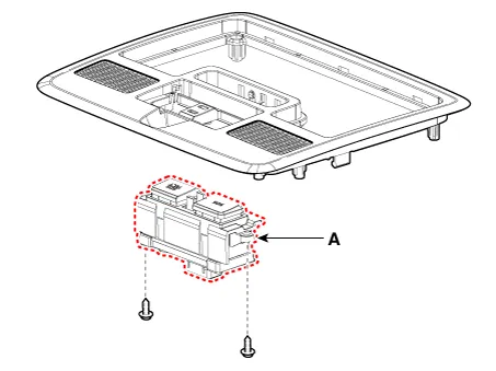
| 6. | Remove the eCall button (A) after loosening the mounting screws.
|
| Installation |
| 1. | Install the eCall button. |
| 2. | Install the map lamp cover. |
| 3. | Connect the map lamp connector. |
| 4. | Install the map lamp. |
| 5. | Install the map lamp lens. |
| 6. | Connect the negative (-) battery terminal. |
Components and components location Component The eCall unit for AVN is equipped in AVN head unit. Repair procedures Removal Carry out the Test Mode in the following cases.
Components and components location Component Location [Engine Room] 1. Engine room relay block [Interior Relay] 1. Interior junction block
Other information:
Kia Picanto (JA) 2017-2026 Service & Repair Manual: Headlamp Leveling System
C
Kia Picanto (JA) 2017-2026 Service & Repair Manual: Rear Combination Lamp
Repair procedures Removal 1.Disconnect the negative (-) battery terminal. 2.Remove the rear combination lamp (A) after loosening the screws. 3.Remove the rear combination lamp packing (A). 4.Disconnect the rear combination lamp connector (A).
Categories
- Manuals Home
- Kia Picanto Owners Manual
- Kia Picanto Service Manual
- Cylinder Head
- Timing Chain
- Suspension System
- New on site
- Most important about car

Copyright © 2026 www.kpicanto.com - 0.0214