Kia Picanto (JA): Drive Belt System / Drive Belt
Repair procedures
| Removal and Installation |
| 1. | Remove the engine room under cover.
(Refer to Engine and Transaxle Assembly - "Engine Room Under Cover")
|
| 2. | Using the wrench, turning the auto tensioner pulley (A) counterclockwise and then insert a stopper pin (B) into the hole.
|
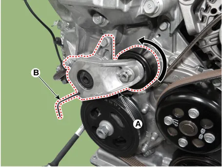
| 3. | Remove the drive belt (A).
|

| 4. | Install in the reverse order of removal. |
| Inspection |
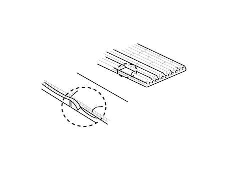
| 1. | Visually check the belt for excessive wear, frayed cords etc. If any defect has been found, replace the drive belt.
|

Repair procedures Removal and Installation 1.Remove the engine room under cover. (Refer to Engine and Transaxle Assembly - "Engine Room Under Cover") 2.
Other information:
Kia Picanto (JA) 2017-2026 Service & Repair Manual: Power Door Lock Module
Components and components location Components 1. Door lock/unlock knob cable 2. Door inside handle cable 3. Door latch assembly Repair procedures Inspection • When removing with a flat-tip screwdriver or remover, wrap protective tape around the tools to prevent damage to
Kia Picanto (JA) 2017-2026 Service & Repair Manual: Rear Glass Defogger Printed Heater
Repair procedures Inspection • Wrap tin foil around the end of the voltmeter test lead to prevent damaging the heater line. Apply pressure on the tin foil with hand and move the tin foil along the grid line to check for open circuits.
Categories
- Manuals Home
- Kia Picanto Owners Manual
- Kia Picanto Service Manual
- Engine Mechanical System
- Engine Oil and Filter
- Normal Condition
- New on site
- Most important about car
