Kia Picanto (JA): Lubrication System / Oil Pan
Repair procedures
| Removal |
| 1. | Remove the engine room under cover.
(Refer to Engine and Transaxle Assembly - “Engine Room Under Cover”)
|
| 2. | Drain the engine oil.
(Refer to Lubrication System - "Engine Oil")
|
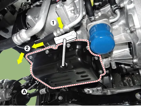
| 3. | Remove the oil pan (A). Insert the blade of SST(09215-3C000) between the ladder frame and the oil pan. Cut out applied sealer and remove the oil pan.
|

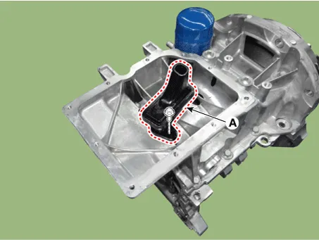
| 4. | Remove the oil screen (A).
|
| Installation |
| 1. | Install the oil screen (A).
|
| 2. | Using a gasket scraper, remove all the old packing material from the gasket surfaces. |
| 3. | Before assembling the oil pan, the liquid sealant should be applied on lower oil pan. Assemble the part within 5 minutes of applying sealant.
|

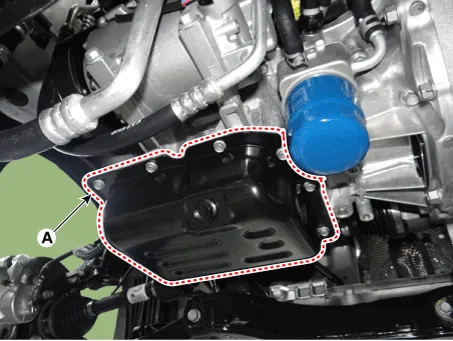
| 4. | Install the oil pan (A). Uniformly tighten the bolts in several passes.
|
| 5. | Install the remaining parts in the reverse order of removal. |
| 6. | Refill with the engine oil.
(Refer to Lubrication System - "Engine Oil")
|
Repair procedures Removal and Installation 1.Remove the engine room under cover. (Refer to Engine and Transaxle Assembly - "Engine Room Under Cover") 2.
Repair procedures Removal and Installation 1.Remove the oil level gauge (A). 2.Remove the timing chain cover & oil pump assembly. (Refer to Timing System - "Timing Chain Cover & Oil Pump Assembly") 3.
Other information:
Kia Picanto (JA) 2017-2026 Service & Repair Manual: Immobilizer Control Unit
Repair procedures Removal 1.Disconnect the negative (-) battery terminal. 2.Remove the main crash pad assembly. (Refer to Body - "Main Crash Pad Assembly") 3.Disconnect the connector of the immobilizer unit and then remove the immobilizer unit (A) after loosening a bolt.
Kia Picanto (JA) 2017-2026 Service & Repair Manual: Hazard Lamp Switch
Repair procedures Inspection 1.Check for continuity between terminals. If the continuity is not as specified, replace the hazard lamp switch. No. Description No.
Categories
- Manuals Home
- Kia Picanto Owners Manual
- Kia Picanto Service Manual
- Clutch Cable
- Engine Mechanical System
- Automatic Transaxle Fluid
- New on site
- Most important about car
