Kia Picanto (JA): Cooling System / Water Temperature Control Assembly
Repair procedures
| Removal |
| 1. | Disconnect the battery negative terminal. |
| 2. | Remove the engine room under cover.
(Refer to Engine and Transaxle Assembly - "Engine Room Under Cover")
|
| 3. | Drain the coolant.
(Refer to Cooling System - "Coolant")
|
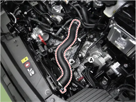
| 4. | Disconnect the radiator upper hose (A).
|
| 5. | Disconnect the heater hoses (A).
|
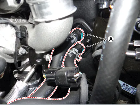
| 6. | Disconnect the water hose (A).
|

| 7. | Disconnect the wiring connectors and harness clamps. Then, remove the connector brackets around the water temperature assembly.
|

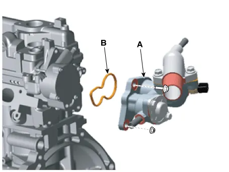
| 8. | Remove the water temperature control assembly (A) with gasket (B).
|

| 9. | Install in the reverse order of removal. |
| 10. | Fill the coolant.
(Refer to Cooling System - "Coolant")
|
| 11. | Start the engine and check for leaks. |
| 12. | Recheck the engine coolant level. |
Repair procedures Removal and Installation 1.Disconnect the negative battery terminal. 2.Remove the engine room under cover and RH side cover. (Refer to Engine and Transaxle Assembly - “Engine Room Under Cover”) 3.
Repair procedures Removal And Installation Thermostat Disassembly of the thermostat would have an adverse effect, causing a lowering of cooling efficiency.
Other information:
Kia Picanto (JA) 2017-2026 Service & Repair Manual: Indicators And Gauges
Troubleshooting Troubleshooting Error Item Failure symptom Inspection items Detailed inspections Relevant Parts/ Components Screen display LCD scree
Kia Picanto (JA) 2017-2026 Service & Repair Manual: Windshield Wiper/Washer
Components and components location Component Location 1. Windshield wiper arm & blade 2. Wiper & washer switch 3. Windshield washer hose & nozzle 4. Wiper motor & linkage assembly 5. Washer motor 6. Washer reservoir tank 7. Wiper/Washer relay 8.
Categories
- Manuals Home
- Kia Picanto Owners Manual
- Kia Picanto Service Manual
- Engine Control / Fuel System
- Body Electrical System
- Battery
- New on site
- Most important about car
