Kia Picanto (JA): Tires/Wheels / Tire
Repair procedures
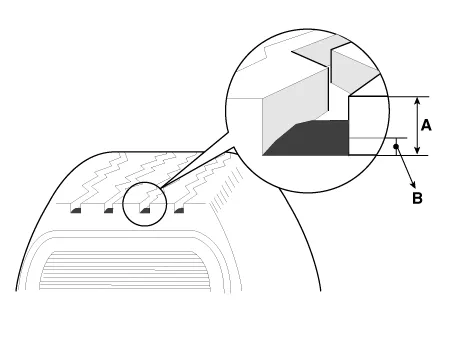
| Tire Wear |
|

| 1. | Measure the tread depth of the tires.
|
| 2. | If the remaining tread depth (A) is less than the limit, replace the tire.
|

| Checking For Pull And Wander |
| 1. | Rotate the front right and front left tires, and perform a road test in order to confirm vehicle stability.
|
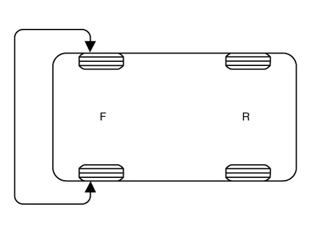
| 2. | If the steering pulls to the opposite side, rotate the front and rear tires, and perform a road test again.
|
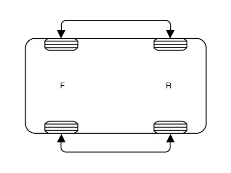
| 3. | If the steering continues to pull to one side, rotate the front right and left tires again, and perform a road test.
|
| 4. | If the steering continues to pull to the opposite side, replace the front wheels with new ones.
|
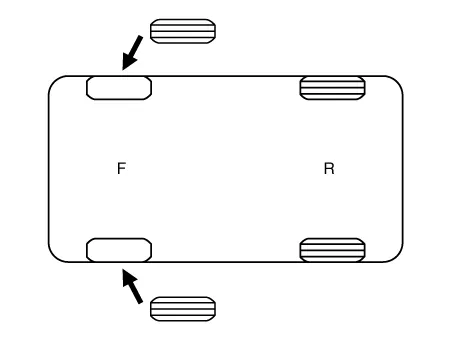
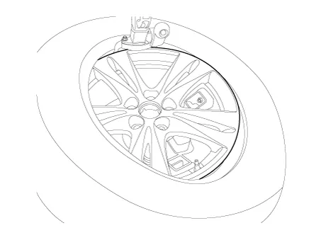
| Removal |
| 1. | Remove the valve core and deflate the tire. |
| 2. | Remove the side of the tire bead area from the wheel using tire changing machine.
|
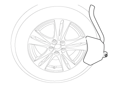
| 3. | Rotate the wheel clockwise.
|


| Installation |
| 1. | Apply tire soap or lubrication to the top and bottom tire beads.
|

| 2. | To fit the bottom bead, position the valve at the 5 o’clock position relative to the head on the tire changing machine.
|
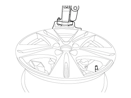
| 3. |
Place the tire on the rim so the bottom bead touches the edge of the
rim after the valve (6 o’clock). Rotate the rim clockwise, and push down
on the tire at the 3 o’clock position to fit bottom bead.
|

| 4. | After
bottom bead is on tire, rotate the rim until the valve is at the 5
o’clock position relative to the head on the tire changing machine. Push
down on the tire at the 3 o’clock position and rotate the rim clockwise
to fit the top bead.
|
| 5. | Inflate the tire until both beads seat.
| |||||||||||||||||||

Repair procedures Hub nut tightening sequence Tighten the hub nuts as follows. Tightening torque: 107.9 - 127.5 N·m (11.0 - 13.
Other information:
Kia Picanto (JA) 2017-2026 Service & Repair Manual: Power Door Mirror Switch
Components and components location Component Schematic diagrams Circuit Diagram [Folding Mirror Type] [Non-Folding Mirror Type] Repair procedures Inspection 1.Check for continuity between the terminals in each switch position according to the table.
Kia Picanto (JA) 2017-2026 Service & Repair Manual: Seat Heater
Components and components location Component Location 1. Seat heater unit 2. Front seat back heater 3. Front seat cushion heater Schematic diagrams Circuit Diagram Repair procedures Inspection 1.Check for continuity and measure the resistance between terminals No 1 and No 4.
Categories
- Manuals Home
- Kia Picanto Owners Manual
- Kia Picanto Service Manual
- To set cruise control speed
- Normal Condition
- Cooling System
- New on site
- Most important about car
