
Kia Picanto (JA): Driveshaft and axle / Rear Axle Assembly
Components and components location
| Components |
| [Disc type] |
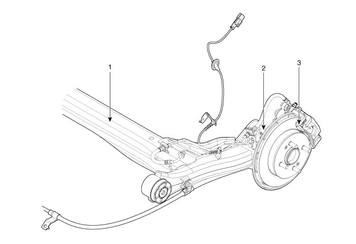
| 1. Tosion beam axle 2. Brake disc | 3. Brake caliper |
| [Drum type] |
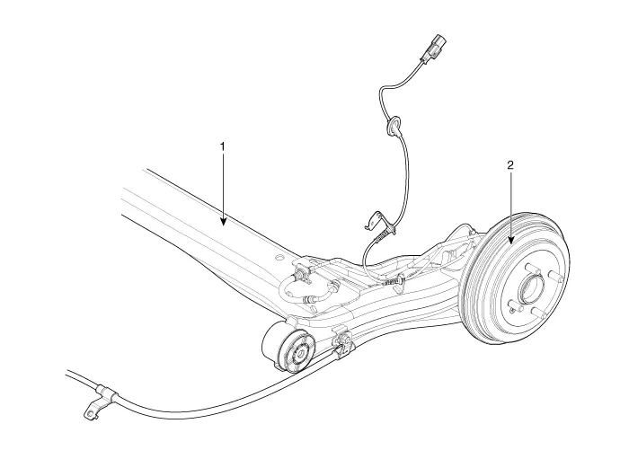
| 1. Tosion beam axle | 2. Drum brake |
Repair procedures
| Removal |
| 1. | Remove the wheel tire (A).
|

| 2. | Remove the rear brake disc caliper.
(Refer to Brake System - "Rear Disc Brake")
|
| 3. | Disconnect the rear wheel speed sensor connector.
|
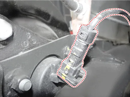
| 4. | Loosen the screw and then remove the rear brake disc.
|

| 5. | Loosen the bolts and then remove the hub (A) from the torsion beam axle.
|

| 6. | Install in the reverse order of removal. |
| 1. | Remove the wheel tire (A).
|
| 2. | Loosen the screw (A) and then remove the brake disc.
|
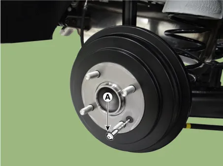
| 3. | Disconnect the wheel speed sensor connector.
|

| 4. | Loosen the bolts and then remove the hub (A) from the torsion beam axle.
|
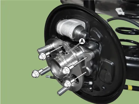
| 5. | Install in the reverse order of removal. |
| Inspection |
| 1. | Check the hub for cracks. |
| 2. | Check the brake disc for scoring and damage. |
| 3. | Check the rear axle carrier for cracks. |
Components and components location Components [RH] 1. BJ assembly 2. Clip 3. BJ boot band 4. BJ boot 5. Dynamic damper band 6. Dynamic damper 7.
Specifications Specification Front Suspension Item Specification Suspension type MacPherson Strut Shock absorber Type General Valve Rear Suspension Item Specification Suspension type Couple Torsion Beam Axle Shock absorber Type General Valve Wheel & Tire Item Specification Front Rear Wheel Aluminum 5.
Other information:
Kia Picanto (JA) 2017-2026 Service & Repair Manual: Emergency Call (eCall) Button
Components and components location Component Repair procedures Removal 1. Disconnect the negative (-) battery terminal. 2. Using a screwdriver or remover, separate the map lamp lens (A) from the map lamp. 3. Remove the map lamp (A) after loosening the screws.
Kia Picanto (JA) 2017-2026 Service & Repair Manual: Map Lamp
Repair procedures Removal • Put on gloves to prevent hand injuries. • When removing with a flat-tip screwdriver or remover, wrap protective tape around the tools to prevent damage to components.
Categories
- Manuals Home
- Kia Picanto Owners Manual
- Kia Picanto Service Manual
- Brake System
- Normal Condition
- Charging System
- New on site
- Most important about car
