Kia Picanto (JA): Ignition System / Ignition Coil
Description and operation
An
ignition coil is an induction coil in an engine's ignition system which
transforms the battery's low voltage to the high voltage needed to
create an electric spark in the spark plugs to ignite the fuel. Coils
have an internal resistor while others rely on a resistor wire or an
external resistor to limit the current flowing into the coil from the
battery 12 V supply.
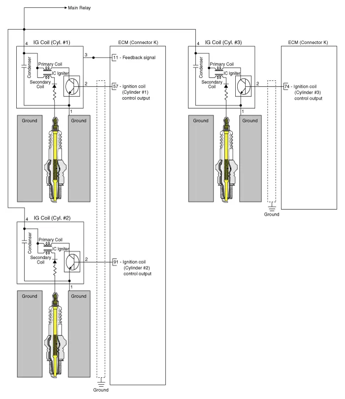
Schematic diagrams

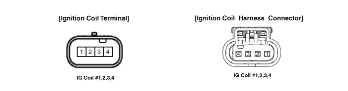
| Ignition Coil Terminal Function |
[A/T]
Ignition Coil (Cylinder #1)
Pin No.
|
Description
|
Connected to
|
1
| Ground
| Chassis
|
2
| ignition Coil #1 Control output
| ECM K(57)
|
3
| -
|
|
4
| Battery power (B+)
| Main Relay
|
Ignition Coil (Cylinder #2)
Pin No.
|
Description
|
Connected to
|
1
| Ground
| Chassis
|
2
| ignition Coil #2 Control output
| ECM K(91)
|
3
| -
|
|
4
| Battery power (B+)
| Main Relay
|
Ignition Coil (Cylinder #3)
Pin No.
|
Description
|
Connected to
|
1
| Ground
| Chassis
|
2
| ignition Coil #3 Control output
| ECM K(74)
|
3
| -
|
|
4
| Battery power (B+)
| Main Relay
|
[M/T]
Ignition Coil (Cylinder #1)
Pin No.
|
Description
|
Connected to
|
1
| Ground
| Chassis
|
2
| ignition Coil #1 Control output
| ECM A(17)
|
3
| -
|
|
4
| Battery power (B+)
| Main Relay
|
Ignition Coil (Cylinder #2)
Pin No.
|
Description
|
Connected to
|
1
| Ground
| Chassis
|
2
| ignition Coil #2 Control output
| ECM A(2)
|
3
| -
|
|
4
| Battery power (B+)
| Main Relay
|
Ignition Coil (Cylinder #3)
Pin No.
|
Description
|
Connected to
|
1
| Ground
| Chassis
|
2
| ignition Coil #3 Control output
| ECM A(1)
|
3
| -
|
|
4
| Battery power (B+)
| Main Relay
|
Repair procedures
| 1. | Turn ignition switch OFF and disconnect the negative (-) battery terminal. |
| 2. | Remove the air cleaner.
(Refer to Engine Mechanical System - "Air Cleaner")
|
| 3. | Disconnect the ignition coil connector (A). |
| 4. | Remove the ignition coil (B) after loosening the mounting bolts.
Ignition coil mounting bolt:
9.8 - 11.8 N·m (1.0 - 1.2 kgf·m, 7.2 - 8.7 Ib·ft) |
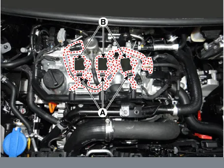 Remove the ignition coil connector by pulling out the lock pin (A) and pushing the clip (B). |
 |
| 1. | Install in the reverse order of removal. |
Description and operation
Description
Ignition timing is controlled by the electronic control ignition timing system.
The
standard reference ignition timing data for the engine operating
conditions are pre-programmed in the memory of the ECM (Engine Control
Module).
Specifications
Specification
Item
Specification
Type ELR11ISPC8+ Gap 0.7 - 0.8 mm (0.
Other information:
Schematic diagrams
Circuit Diaram
Description and operation
Description
The
immobilizer system will disable the vehicle unless the proper ignition
key is used, in addition to the currently available anti-theft systems
such as car alarms, the immobilizer system aims to drastically reduce
the rate of auto theft.
Repair procedures
Inspection
1.Check for continuity between terminals. If the continuity is not as specified, replace the hazard lamp switch.
No.
Description
No.

