Kia Picanto (JA): ISG (Idle Stop & Go) System / Alternator
Specifications
| Specification |
|
Item
|
Specification
|
| Rated voltage | 13.5V, 130A |
| Speed in use | 1,000 - 18,000 rpm |
| Voltage regulator | IC Regulator built-in type |
| ECM Interface type regulator | LIN communication |
| Regulator Setting Voltage (Internal mode) | 14.5 ± 0.3V |
| Connector | 1 Pin (COM) |
| Pulley Type | OAP |
OAP : Overruning Alternator Pulley |

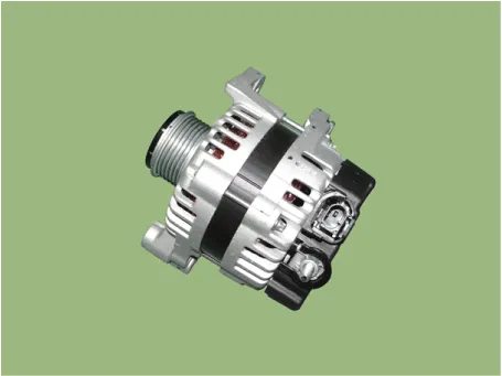
Components and components location
| Component |
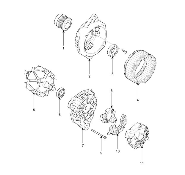
| 1. Pully 2. Front Bracket 3. Front Bearing 4. Stator 5. Rotor 6. Rear Bearing | 7. Rear Bracket 8. Brush Holder Assembly 9. Through Bolt 10. Rectifier Assembly 11. Rear Cover |
Description and operation
| Description |
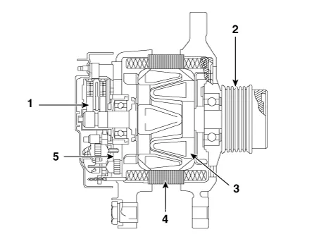
| 1. Brush 2. OAP : Overruning Alternator Pulley 3. Rotor 4. Stator 5. Rectifier |
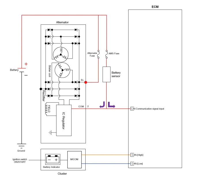
Schematic diagrams
| Circuit Diagram |
|
Repair procedures
| Removal |
| 1. | Turn ignition switch OFF and disconnect the negative (-) battery terminal. |
| 2. | Remove the air cleaner.
(Refer to Engine Mechanical System - "Air Cleaner")
|
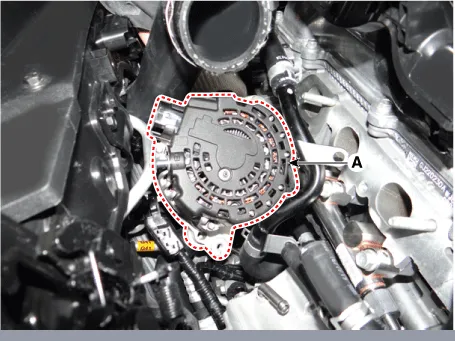
| 3. | Disconnect the alternator connector (A) and alternator "B" cable (B) from the terminal.
|

| 4. | Remove the drive belt.
(Refer to Engine Mechanical System - "Drive Belt")
|
| 5. | Remove the intake manifold.
(Refer to Engine Mechanical System - "Intake Manifold")
|
| 6. | Remove the alternator mounting bolts (A).
|
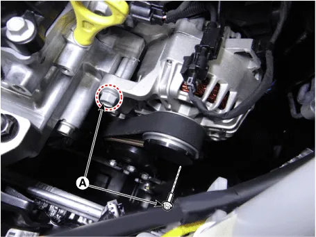
| 7. | Remove the alternator (A).
|
| Installation |
| 1. | Install in the reverse order of removal. |
| 2. | Adjust the alternator belt tension after installation.
(Refer to Engine Mechanical System - "Drive Belt")
|
| 3. | Install the alternator. |
| Disassembly |
| 1. | Remove the rear cover (A).
|


| 2. | Remove the regulator assembly (A) after loosening the mounting bolts.
|


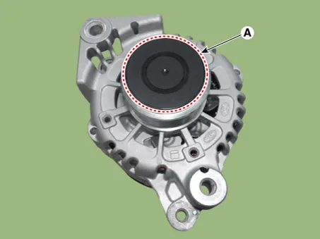
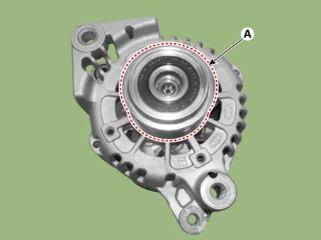
| 3. | Remove the OAP cap (A).
|
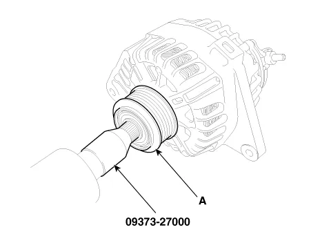
| 4. | Using the SST (09373-27000), remove the OAP pulley (A).
|
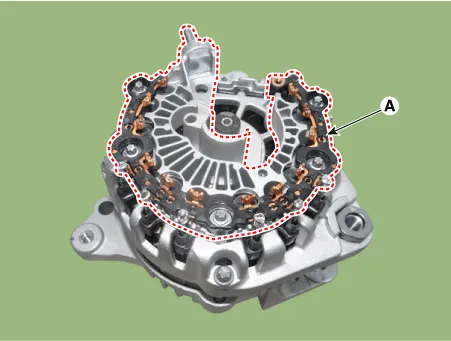
| 5. | Remove the rectifier assembly (A) after disconnecting the stator leads.
|
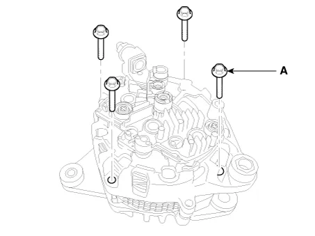
| 6. | Loosen the through bolts (A).
|
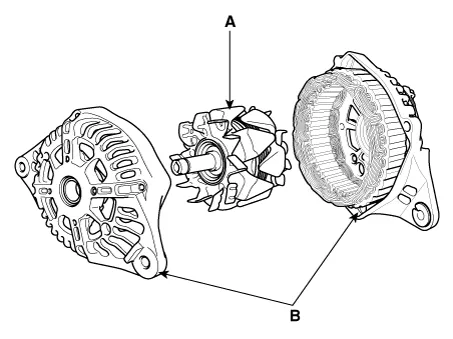
| 7. | Disconnect the rotor (A) and housing (B).
|
| Reassembly |
| 1. | Reassemble in the reverse order of disassembly.
|
| Inspection |
| [Rotor] |
| 1. | Check for continuity between the slip rings (C).
|
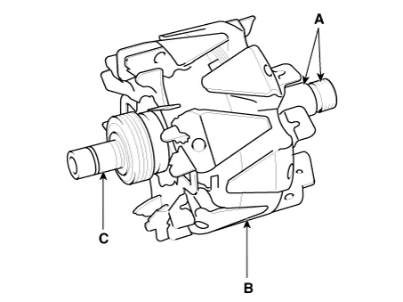
| 2. | Check that there is no continuity between the slip rings and the rotor (B) or rotor shaft (A). |
| 3. | If the rotor fails either continuity checks, replace the alternator. |
| [Stator] |
| 1. | Check that there is continuity between each pair of leads (A).
|
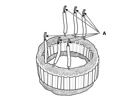
| 2. | Check that there is no continuity between each lead and the coil core. |
| 3. | If the coil fails either continuity checks, replace the alternator. |
Components and components location Components 1. ISG OFF switch Description and operation Description The ISG OFF switch on the floor console can be used to deactivate the ISG function.
Specifications Specification ▷12V, 1.2kW : ISG only Item Specification Rated voltage 12 V, 1.
Other information:
Kia Picanto (JA) 2017-2026 Service & Repair Manual: Junction Box (Engine Compartment)
Components and components location Component Location E/R Junction Box Circuit (E/R Junction Block) E/R Junction Box Circuit (E/R Junction Block) Repair procedures Inspection 1. Disconnect the negative (-) battery terminal.
Kia Picanto (JA) 2017-2026 Service & Repair Manual: Parking Assist Sensor
Components and components location Components Repair procedures Removal 1.Disconnect the negative (-) battery terminal. 2.Remove the rear bumper assembly. (Refer to Body - "Rear Bumper Assembly") 3.Disconnect the connector (A) from the ultrasonic sensor.
Categories
- Manuals Home
- Kia Picanto Owners Manual
- Kia Picanto Service Manual
- Engine Mechanical System
- Thermostat
- Body Electrical System
- New on site
- Most important about car
