Kia Picanto (JA): Charging System / Alternator
Specifications
| Specification |
|
Item
|
Specification
|
| Rated voltage | 13.5V, 120A |
| Speed in use | 1,000 - 18,000 rpm |
| Voltage regulator | IC Regulator built-in type |
| ECM Interface type regulator | LIN communication |
| Regulator Setting Voltage (Internal mode) | 14.5 ± 0.3V |
| Connector | 1 Pin (COM) |
| Pulley Type | OAP |
|
Item
|
Specification
|
| Rated voltage | 13.5V, 90A |
| Speed in use | 1,000 - 18,000 rpm |
| Voltage regulator | IC Regulator built-in type |
| ECM Interface type regulator | LIN communication |
| Regulator Setting Voltage (Internal mode) | 14.5 ± 0.3V |
| Connector | 1 Pin (COM) |
| Pulley Type | OAP |
OAP : Overruning Alternator Pulley |

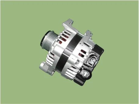
Components and components location
| Component |
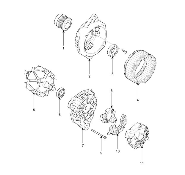
| 1. Pully 2. Front Bracket 3. Front Bearing 4. Stator 5. Rotor 6. Rear Bearing | 7. Rear Bracket 8. Brush Holder Assembly 9. Through Bolt 10. Rectifier Assembly 11. Rear Cover |
Description and operation
| Description |
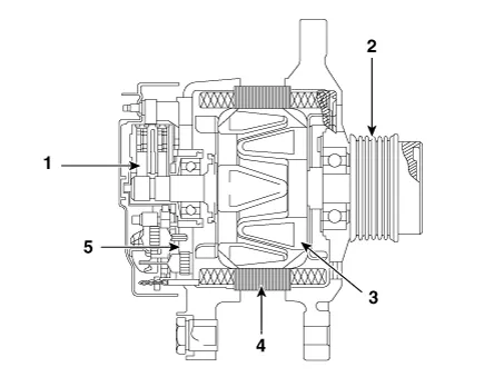
| 1. Brush 2. OAP : Overruning Alternator Pulley 3. Rotor 4. Stator 5. Rectifier |
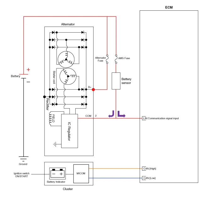
Schematic diagrams
| Circuit Diagram |
|
Repair procedures
| Removal |
| 1. | Turn ignition switch OFF and disconnect the negative (-) battery terminal. |
| 2. | Remove the air cleaner. (Refer to Engine Mechanical System - "Air Cleaner") |
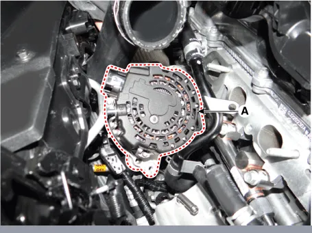
| 3. | Disconnect the alternator connector (A) and alternator "B" cable (B) from the terminal.
|

| 4. | Remove the drive belt. (Refer to Engine Mechanical System - "Drive Belt") |
| 5. | Remove the intake manifold. (Refer to Engine Mechanical System - "Intake Manifold") |
| 6. | Remove the alternator mounting bolts (A).
|
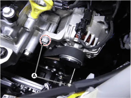
| 7. | Remove the alternator (A).
|
| Installation |
| 1. | Install in the reverse order of removal. |
| Disassembly |
| 1. | Remove the rear cover (A).
|


| 2. | Remove the regulator assembly (A) after loosening the mounting bolts.
|


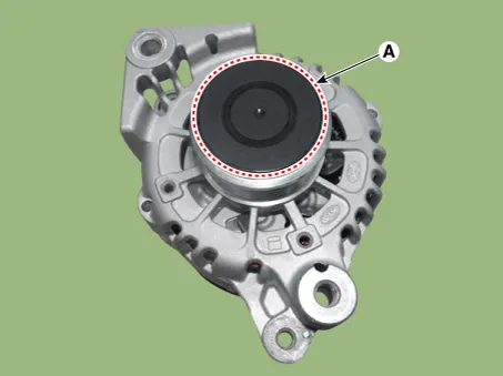
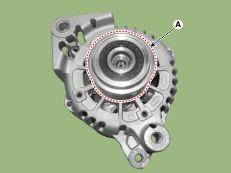
| 3. | Remove the OAP cap (A).
|
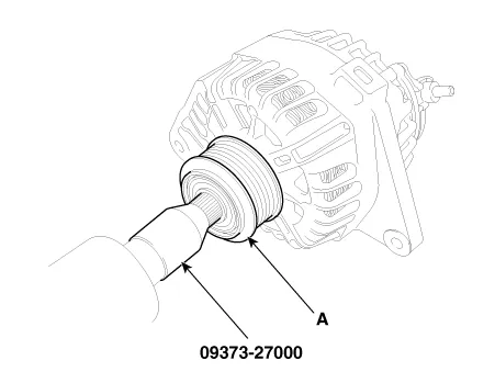
| 4. | Using the SST (09373-27000), remove the OAP pulley (A).
|
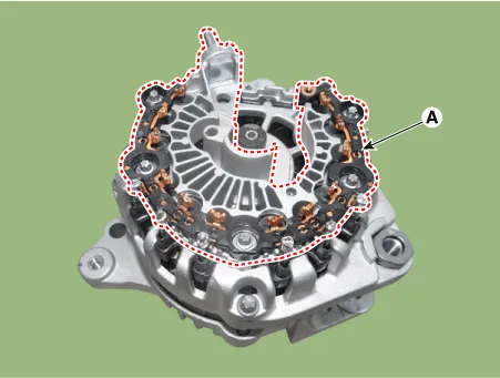
| 5. | Remove the rectifier assembly (A) after disconnecting the stator leads.
|
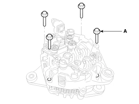
| 6. | Loosen the through bolts (A).
|
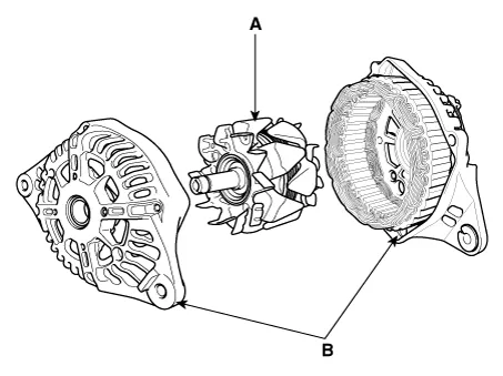
| 7. | Disconnect the rotor (A) and housing (B).
|
| Reassembly |
| 1. | Reassemble in the reverse order of disassembly.
|
| Inspection |
| [Rotor] |
| 1. | Check for continuity between the slip rings (C).
|
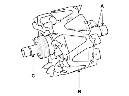
| 2. | Check that there is no continuity between the slip rings and the rotor (B) or rotor shaft (A). |
| 3. | If the rotor fails either continuity checks, replace the alternator. |
| [Stator] |
| 1. | Check that there is continuity between each pair of leads (A).
|
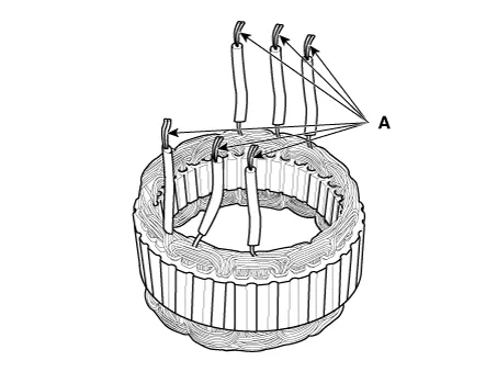
| 2. | Check that there is no continuity between each lead and the coil core. |
| 3. | If the coil fails either continuity checks, replace the alternator. |
Components and components location Components ① ECM ② Battery ③ Alternator ④ Starter ⑤ Instrument Cluster ⑥ Ignition switch or start/stop button ⑦ Battery sensor ⑧ Hood switch Description and operation Description The charging system consists of a battery, an alternator with a built-in regulator, and the charging indicator light and wire.
Description and operation Description Due to the considerably more frequent occurrence of starting operations, the electrical load that occurs often leads to voltage dips in the vehicle network.
Other information:
Kia Picanto (JA) 2017-2026 Service & Repair Manual: Sunroof Motor
Repair procedures Inspection 1.Disconnect the negative (-) battery terminal. 2.Remove the roof trim assembly. (Refer to Body - "Roof Trim Assembly") 3.Remove the glass motor (A) after loosening the mounting screws. 4.
Kia Picanto (JA) 2017-2026 Service & Repair Manual: Mode Control Actuator
Components and components location Component Location 1. Mode Control Actuator Description and operation Description The mode control actuator is located at the heater unit. It adjusts position of mode door by operating mode control actuator based on signal of A/C control unit.
Categories
- Manuals Home
- Kia Picanto Owners Manual
- Kia Picanto Service Manual
- Coolant
- Fuel Delivery System
- Engine Control / Fuel System
- New on site
- Most important about car
