Kia Picanto (JA): Light bulbs / Headlamp and front fog lamp aiming (for Europe)
Headlamp aiming
1. Inflate the tires to the specified pressure and remove any loads from the vehicle except the driver, spare tire, and tools.
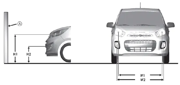
2. The vehicle should be placed on a flat floor.
3. Draw vertical lines (Vertical lines passing through respective head lamp centers) and a horizontal line (Horizontal line passing through center of head lamps) on the screen.
4. With the head lamp and battery in normal condition, aim the head lamps so the brightest portion falls on the horizontal and vertical lines.
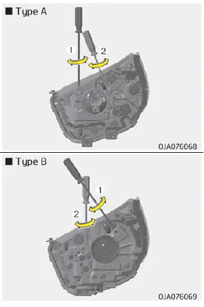
5. To aim the low and high beams left or right, turn the driver (1) clockwise or counterclockwise. To aim the low and high beams up or down, turn the driver (2) clockwise or counterclockwise.
Front fog lamp aiming

The front fog lamp can be aimed as the same manner of the head lamps aiming.
With the front fog lamps and battery normal condition, aim the front fog lamps.
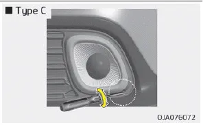
To aim the front fog lamp up or down, turn the driver clockwise or counterclockwise.
Aiming point
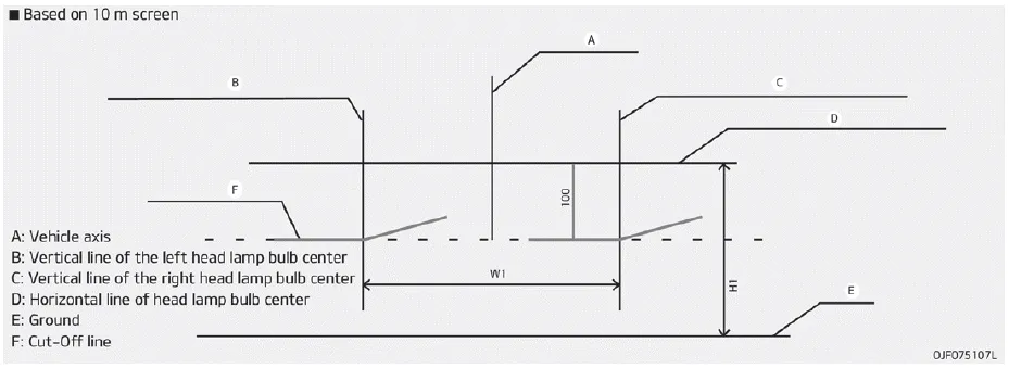
Head lamp low beam (LHD Vehicle)
1. Turn the low beam on without driver aboard.
2. The cut-off line should be projected in the cut-off line shown in the
picture.
3. When aiming the low beam, vertical aiming should be adjusted after adjusting
the horizontal aiming.
4. If head lamp leveling device is equipped, adjust the head lamp leveling
device switch with 0 positions.

Head lamp low beam (RHD Vehicle)
1. Turn the low beam on without driver aboard.
2. The cut-off line should be projected in the cut-off line shown in the
picture.
3. When aiming the low beam, vertical aiming should be adjusted after adjusting
the horizontal aiming.
4. If head lamp leveling device is equipped, adjust the head lamp leveling
device switch with 0 positions.
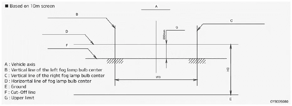
Front fog lamp
1. Turn the front fog lamp on without the driver aboard.
2. The cut-off line should be projected in the allowable range (shaded region).
1. Using a flat-blade screwdriver, gently pry the lens cover from lamp housing. 2. Remove the bulb by pulling it straight out. 3. Install a new bulb in the socket.
Other information:
Kia Picanto (JA) 2017-2026 Service & Repair Manual: Start/Stop Button
Components and components location Component Repair procedures Removal 1.Disconnect the negative (-) battery terminal. 2.Remove the crash pad lower panel. (Refer to Body - "Crash Pad Lower Panel") 3.Remove the steering column shroud lower panel.
Kia Picanto (JA) 2017-2026 Service & Repair Manual: Front Washer Motor
Repair procedures Inspection Front Washer Motor 1.With the washer motor connected to the reservoir tank, fill the reservoir tank with water. • Before filling the reservoir tank with water, check the filter for foreign material or contamination.
Categories
- Manuals Home
- Kia Picanto Owners Manual
- Kia Picanto Service Manual
- Heating,Ventilation, Air Conditioning
- Gasoline reservoir in the engine room
- Engine Control / Fuel System
- New on site
- Most important about car
