
Kia Picanto (JA): Chassis / Brake/Clutch Fluid
Repair procedures
| Inspection |
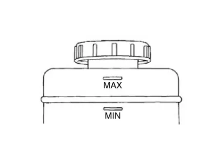
Repair procedures Inspection Visually check for proper installation, chafing, cracks, deterioration and any leakage. Replace any deteriorated or damaged parts immediately.
Other information:
Kia Picanto (JA) 2017-2026 Service & Repair Manual: Start/Stop Button
Components and components location Component Repair procedures Removal 1.Disconnect the negative (-) battery terminal. 2.Remove the crash pad lower panel. (Refer to Body - "Crash Pad Lower Panel") 3.Remove the steering column shroud lower panel.
Kia Picanto (JA) 2017-2026 Service & Repair Manual: Power Windows
Components and components location Component Location 1. Driver power window switch 2. Assist power window switch 3. Rear power window switch 4. Front window motor 5. Rear window motor Description and operation Safety Function of Power Window When driver door power window auto-up switch is operated, safety function is acti
Categories
- Manuals Home
- Kia Picanto Owners Manual
- Kia Picanto Service Manual
- Thermostat
- Engine Control / Fuel System
- Fuel Delivery System
- New on site
- Most important about car
