Kia Picanto (JA): Audio / Audio Unit
Components and components location
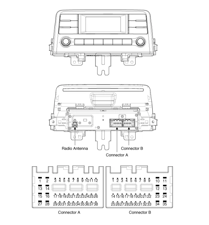
| Components |
| [Radio/MP3/Bluetooth (A Type)] |
|
No.
|
Connector A
|
Connector B
|
| 1 | Rear door left speaker (+) | - |
| 2 | Rear door left speaker (-) | MIC (+) |
| 3 | USB Ground | - |
| 4 | USB Data (+) | Detent |
| 5 | USB Data (-) | Antenna power |
| 6 | USB VCC | Illumination (+) |
| 7 | - | Non E-Call type : - E-Call type : Multmedia-CAN (High) |
| 8 | - | - |
| 9 | - | - |
| 10 | AUX Audio_right input | Battery (+) |
| 11 | AUX Detect | Battery (+) |
| 12 | Steering wheel remote controller | Ground |
| 13 | Front door left speaker (+) | Ground |
| 14 | Front door left speaker (-) | - |
| 15 | Front door right speaker (-) | MIC (-) |
| 16 | Front door right speaker (+) | - |
| 17 | - | - |
| 18 | - | Vehicle speed |
| 19 | - | Illumination (-) |
| 20 | - | Non E-Call type : - E-Call type : Multmedia-CAN (Low) |
| 21 | - | - |
| 22 | - | ACC |
| 23 | - | - |
| 24 | AUX Audio_left input | - |
| 25 | AUX Audio_Ground | - |
| 26 | Steering wheel remote controller (Ground) | - |
| 27 | Rear door right speaker (-) | - |
| 28 | Rear door right speaker (+) | - |
| 29 | - | - |
| 30 | - | - |
| 31 | - | - |
| 32 | - | - |
| 33 | - | - |
| 34 | - | - |
| 35 | - | - |
| 36 | - | |
| 37 | - | |
| 38 | - |

| [Radio/MP3/Bluetooth (B Type)] |

|
No.
|
Connector A
|
Connector B
|
| 1 | Rear door left speaker (+) | - |
| 2 | Rear door left speaker (-) | MIC (+) |
| 3 | - | - |
| 4 | - | - |
| 5 | - | Antenna power |
| 6 | Camera power | Illumination (+) |
| 7 | Camera video | Non E-Call type : - E-Call type : Multmedia-CAN (High) |
| 8 | - | - |
| 9 | - | ALT Left_output (-) |
| 10 | AUX Audio_right input | Battery (+) |
| 11 | AUX Detect | Battery (+) |
| 12 | Steering wheel remote controller | Ground |
| 13 | Front door left speaker (+) | Ground |
| 14 | Front door left speaker (-) | MIC Ground |
| 15 | Front door right speaker (-) | MIC (-) |
| 16 | Front door right speaker (+) | - |
| 17 | - | - |
| 18 | - | - |
| 19 | - | Illumination (-) |
| 20 | Camera power_Ground | Non E-Call type : - E-Call type : Multmedia-CAN (Low) |
| 21 | Camera video_Ground | - |
| 22 | - | ACC |
| 23 | - | - |
| 24 | AUX Audio_left input | - |
| 25 | AUX Audio_Ground | Reverse |
| 26 | Steering wheel remote controller (Ground) | Door open |
| 27 | Rear door right speaker (-) | Door unlock |
| 28 | Rear door right speaker (+) | Parking brake |
| 29 | - | 'P' Position |
| 30 | - | AV Tail |
| 31 | - | - |
| 32 | - | - |
| 33 | Camera VIN_Shield | IGN1 |
| 34 | - | - |
| 35 | - | - |
| 36 | - | |
| 37 | - | |
| 38 | Vehicle speed |

Repair procedures
| Removal |
|

| 1. | Disconnect the negative (-) battery terminal. |
| 2. | Remove the center fascia panal.
(Refer to Body - "Center Fascia Panel")
|
| 3. | Remove the audio head unit (A) after loosening the mounting screws and nut.
|

| 4. | Remove the audio head unit after disconnecting the connectors and antenna cable (A).
|


| Installation |
| 1. | Connect the audio unit connectors and antenna cable. |
| 2. | Install the audio head unit. |
| 3. | Install the center fascia panel. |
| 4. | Connect the negative (-) battery terminal.
|
Specifications Specifications Items Specifications Model Radio /MP3 /Bluetooth (A Type) Radio /MP3 /Bluetooth (B Type) Power supply DC 14.
Repair procedures Inspection Troubleshooting of the speakers When handling the speakers :• Do not cause shock to the speakers by dropping or throwing them.
Other information:
Kia Picanto (JA) 2017-2026 Service & Repair Manual: Antenna Coil
Repair procedures Removal 1.Disconnect the negative (-) battery terminal. 2.Remove the crash pad lower panel. (Refer to Body - "Crash Pad Lower Panel") 3.Remove the steering column upper and lower shroud panel. (Refer to Body - "Steering Column Shroud Panel") 4.
Kia Picanto (JA) 2017-2026 Service & Repair Manual: Rear Washer Switch
Repair procedures Inspection Multifunction Switch Inspection 1. Check for continuity between the terminals in each switch position as shown below. Rear Wiper & Washer Switch[LHD] [RHD] Inspection (With KDS/GDS) 1. In the body electrical system, failure can be quickly diagnosed by using the vehicle diagnostic system (KDS/GDS).
Categories
- Manuals Home
- Kia Picanto Owners Manual
- Kia Picanto Service Manual
- General Information
- Charging System
- Cylinder Head
- New on site
- Most important about car
