Kia Picanto (JA): Cylinder Head Assembly / Vacuum Pump
Repair procedures
| Removal and Installation |
| 1. | Disconnect the battery negative terminal. |
| 2. | Disconnect the wiring connectors and harness clamps and remove the connector brackets around the vacuum pump.
|

| 3. | Remove the air cleaner assembly.
(Refer to Intake and Exhaust System - "Air Cleaner")
|
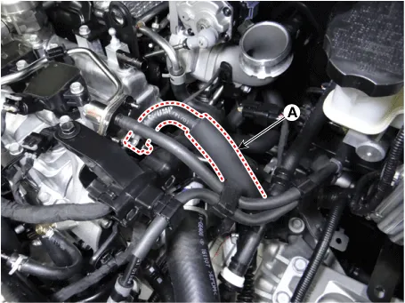
| 4. | Disconnect the brake booster vacuum hose (A).
|
| 5. | Remove the wiring bracket (A) and then remove the vacuum pump (B).
|

| 6. | Install in the reverse order of removal. |
Components and components location Components 1. Oil filler cap 2. Cylinder head cover 3. Cylinder head cover gasket Repair procedures Removal • Use fender covers to avoid damaging painted surfaces.
Description and operation Description Continuous Variable Valve Timing (CVVT) system advances or retards the valve timing of the intake and exhaust valve in accordance with the ECM control signal which is calculated by the engine speed and load.
Other information:
Kia Picanto (JA) 2017-2026 Service & Repair Manual: Back View Camera System
Components and components location Component Location 1. Back view camera 2. AVN head unit 3. steering angle sensor Description and operation Description 1. To display back of the vehicle to assist the driver, it receives vehicle rearside image signal from the rearview camera and displays it on AVN head unit monitor
Kia Picanto (JA) 2017-2026 Service & Repair Manual: Emergency Call System
Components and components location Components 1. Head unit (AVN, Audio) 2. Emergency call system button 3. Emergency call system MIC 4. Roof antenna 5. Emergency call unit 6. Supplemental Restraint System Control Module (SRSCM) 7. Emergency call crash pad antenna 8.
Categories
- Manuals Home
- Kia Picanto Owners Manual
- Kia Picanto Service Manual
- Engine Mechanical System
- Normal Condition
- Body Electrical System
- New on site
- Most important about car
