Kia Picanto (JA): Timing System / Timing Chain
Repair procedures
| Removal |
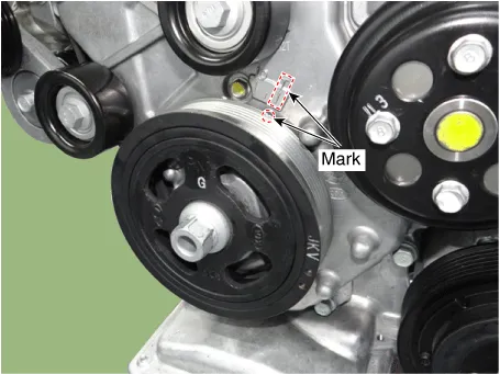
| 1. | Turn
the crankshaft pulley and align its groove with the timing mark of the
chain cover & oil pump assembly to set the piston of No.1 cylinder
to the top dead center on compression stroke.
|
| 2. | Remove the timing chain cover & oil pump assembly.
(Refer to Timing System - "Timing Chain Cover & Oil Pump Assembly")
|
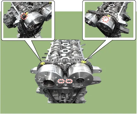
| 3. | Before
removing the timing chain, mark the timing chain with an identification
based on the location of the sprocket because the identification mark
on the chain for TDC (Top Dead Center) can be erased.
|
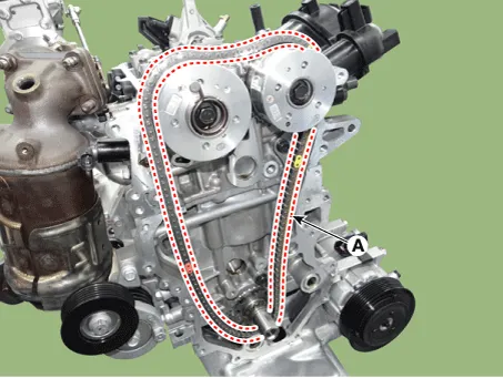
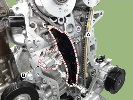
| 4. | Remove the timing chain auto tensioner (A) and then remove the tensioner arm (B).
|


| 5. | Remove the timing chain (A).
|
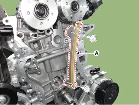
| 6. | Remove the timing chain guide (A).
|
| Inspection |
| 1. | Inspect the tensioner arm and chain guide for abnormal wear, cracks, or damage. Replace as necessary. |
| 2. | Check that the tensioner piston moves smoothly. |
| Installation |
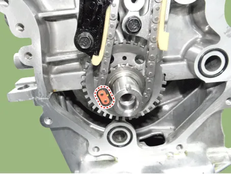
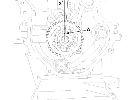
| 1. | Set
the dowel pin (A) of crankshaft about 3° with vertical center line. As a
result of this, the piston of No.1 cylinder is placed at the top dead
center on compression stroke.
|
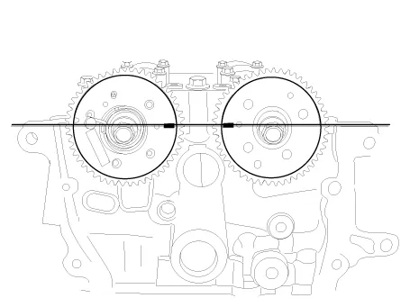
| 2. | Align
the mark of the exhaust camshaft sprocket and intake CVVT on the top
surface of cylinder head. As a result of this, the piston of No.1
cylinder is placed at the top dead center on compression stroke.
|
| 3. | Install the timing chain guide (A).
|
| 4. | Install the timing chain (A).
|

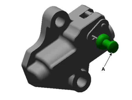
| 5. | Install the timing chain tensioner arm (A) and the timing chain tensioner (B) and then remove the stopper pin.
|
| 6. | After rotating the crankshaft 2 revolutions in regular direction (clockwise viewed from front), confirm the timing mark.
|
| 7. | Install the remaining parts in the reverse order of removal. |
Repair procedures Removal Engine removal is not required for this procedure. • Use fender covers to avoid damaging painted surfaces.
Specifications Specification Ignition System Spark plug Item Specification Type ELR11ISPC8+ Gap 0.
Other information:
Kia Picanto (JA) 2017-2026 Service & Repair Manual: Immobilizer System
Schematic diagrams Circuit Diaram Description and operation Description The immobilizer system will disable the vehicle unless the proper ignition key is used, in addition to the currently available anti-theft systems such as car alarms, the immobilizer system aims to drastically reduce the rate of auto theft.
Kia Picanto (JA) 2017-2026 Service & Repair Manual: Rear Washer Motor
Repair procedures Inspection 1.With the washer motor connected to the reservoir tank, fill the reservoir tank with water. Before filling the reservoir tank with water, check the filter for foreign material or contamination.
Categories
- Manuals Home
- Kia Picanto Owners Manual
- Kia Picanto Service Manual
- Timing Chain
- Charging System
- Engine Oil and Filter
- New on site
- Most important about car
