
Kia Picanto (JA): Rear Suspension System / Rear Coil Spring
Repair procedures
| Replacement |
| 1. | Remove the wheel tire (A).
|


| 2. | Loosen the bolt and then remove the rear shock absorber.
|
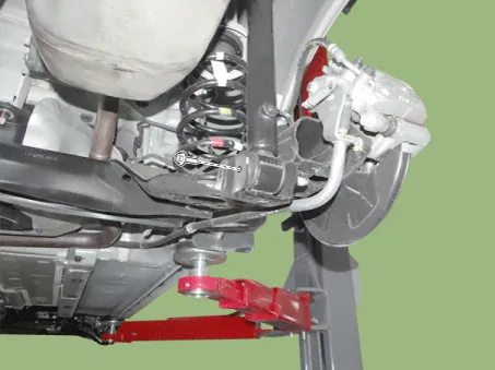

| 3. | Remove the rear coil spring. |
| 4. | Install in the reverse order of removal. |
| Inspection |
| 1. | Check the coil spring for crack and deformation. |
| 2. | Check the coil spring pad for damage and deformation. |
Components and components location Components 1. Cover 2. Lock nut 3. Retainer 4. Upper bushing 5. Collar 6. Lower bushing 7. Upper cover 8. Bumper stopper 9.
Components and components location Components [Disc type] 1. Torsion beam axle 2. Brake disc 3. Brake caliper [Drum type] 1. Torsion beam axle 2.
Other information:
Kia Picanto (JA) 2017-2026 Service & Repair Manual: Rear Wiper Motor
Repair procedures Inspection Rear Wiper Motor 1.Remove the connector from the rear wiper motor. 2.Connect positive (+) battery cables to terminal 1 and negative (-) battery cables to terminal 2 respectively. 3.Check that the motor operates normally.
Kia Picanto (JA) 2017-2026 Service & Repair Manual: Heater Core
Repair procedures Replacement 1.Disconnect the negative (-) battery terminal. 2.Remove the heater unit. (Refer to Heater - "Heater Unit") 3.Remove the heater core cover (A) after loosening the mounting screws. 4.Pull out the heater core (A) from the heater unit.
Categories
- Manuals Home
- Kia Picanto Owners Manual
- Kia Picanto Service Manual
- Fuel Delivery System
- Suspension System
- Engine Oil and Filter
- New on site
- Most important about car
