Kia Picanto (JA): ISG (Idle Stop & Go) System / ISG OFF switch
Components and components location
| Components |
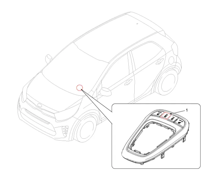
| 1. ISG OFF switch |
Description and operation
| Description |
Schematic diagrams
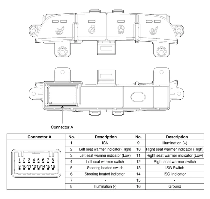
| Circuit Diagram |
Repair procedures
| Removal |
| 1. | Turn ignition switch OFF and disconnect the battery negative (-) terminal. |
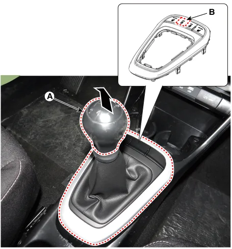
| 2. | Remove the knob (A) by pulling it in the direction of arrow. |
| 3. | Using a remover, remove the console indicator cover assembly (B).
|
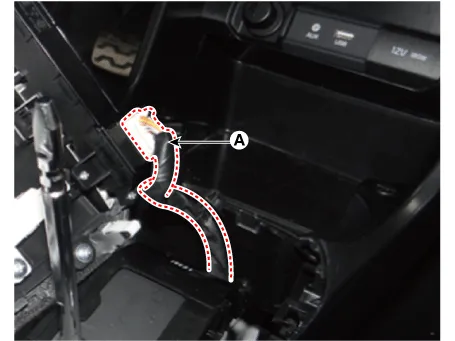
| 4. | Disconnect the connector (A) from the console indicator cover assembly.
|
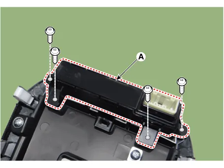
| 5. | Remove the console upper cover switch (A) after loosening the mounting screws.
|
| Installation |
| 1. | Install the console upper cover switch. |
| 2. | Connect the console indicator cover assembly connector. |
| 3. | Install the console indicator cover assembly. |
| 4. | Install the gear knob & gear boots. |
| 5. | Connect the negative (-) battery terminal. |
Description and operation Description Due to the considerably more frequent occurrence of starting operations, the electrical load that occurs often leads to voltage dips in the vehicle network.
Specifications Specification ▷ 13.5V, 130A [ISG only] Item Specification Rated voltage 13.
Other information:
Kia Picanto (JA) 2017-2026 Service & Repair Manual: Lighting System
Specifications Specification Item Type Bulb Watt (W) Front Headlamp Halogen (Position lamp) Low/High H4 LL 55/60 Turn signal lamp PY21WLL 21 Position lamp W5WLL 5 Halogen (Position lamp + DRL) Low/High HB3 (9005HL+) 60 Turn signal lamp LED LED Po
Kia Picanto (JA) 2017-2026 Service & Repair Manual: Power Mosfet
Repair procedures Inspection 1.Ignition "ON" 2.Manually operate the control switch and measure the voltage of blower motor. 3.Select the control switch to raise voltage until high speed. Fan Motor Voltage ManualFirst speed3.
Categories
- Manuals Home
- Kia Picanto Owners Manual
- Kia Picanto Service Manual
- Clutch Cable
- Automatic Transaxle Fluid
- Thermostat
- New on site
- Most important about car
