Kia Picanto (JA): Immobilizer System / Immobilizer Control Unit
Repair procedures
| Removal |
| 1. | Disconnect the negative (-) battery terminal. |
| 2. | Remove the main crash pad assembly.
(Refer to Body - "Main Crash Pad Assembly")
|
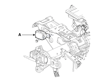
| 3. | Disconnect the connector of the immobilizer unit and then remove the immobilizer unit (A) after loosening a bolt.
|
| Installation |
| 1. | Install the immobilizer control unit after connecting the unit connector. |
| 2. | Install the main crash pad assembly. |
| 3. | Connect the negative (-) battery terminal. |
Schematic diagrams Circuit Diaram Description and operation Description The immobilizer system will disable the vehicle unless the proper ignition key is used, in addition to the currently available anti-theft systems such as car alarms, the immobilizer system aims to drastically reduce the rate of auto theft.
Repair procedures Removal 1.Disconnect the negative (-) battery terminal. 2.Remove the crash pad lower panel. (Refer to Body - "Crash Pad Lower Panel") 3.
Other information:
Kia Picanto (JA) 2017-2026 Service & Repair Manual: Junction Box (Passenger Compartment)
Components and components location Component Location I/P Junction Box Circuit (I/P Junction Box) Description and operation Description Communication Network Diagram Abbreviation Explanation ABS Anti-lock Brake System ACU Airbag Control Un
Kia Picanto (JA) 2017-2026 Service & Repair Manual: Temperature Control Actuator
Components and components location Component Location 1. Temerature Control Actuator Description and operation Description 1. Heater unit includes mode control actuator and temperature control actuator. 2. Temperature control actuator is located at the heater unit.
Categories
- Manuals Home
- Kia Picanto Owners Manual
- Kia Picanto Service Manual
- Timing Chain
- Engine Oil and Filter
- Maintenance
- New on site
- Most important about car
