Kia Picanto (JA): Engine And Transaxle Assembly / Engine And Transaxle Assembly
Repair procedures
| Removal |
|

|

| 1. | Remove the air cleaner assembly.
(Refer to Intake and Exhaust System - "Air Cleaner")
|
| 2. | Remove the engine room under cover and side cover.
(Refer to Engine and Transaxle Assembly - Engine Room Under Cover")
|
| 3. | Drain the coolant.
(Refer to Cooling System - "Coolant")
|
| 4. | Recover the refrigerant and then remove the high pressure pipe and low pressure pipe.
(Refer to Heating, Ventilation Air conditioning - "Compressor")
|
| 5. | Remove the battery and battery tray.
(Refer to Engine Electrical System - "Battery")
|
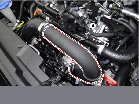
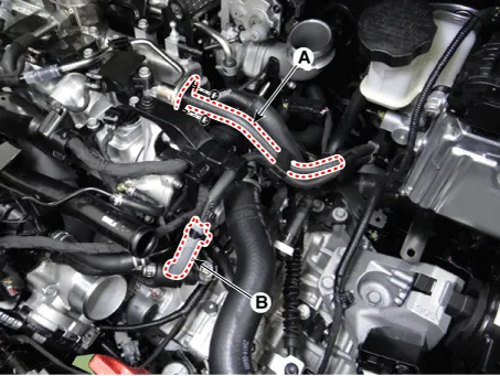
| 6. | Remove the intercooler inlet hoses & pipe (A).
|
| 7. | Disconnect the intercooler outlet hose & pipe (A)
|
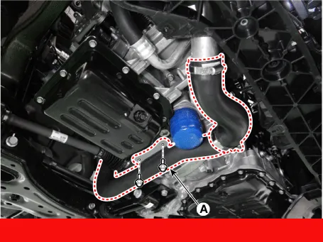
| 8. | Disconnect the water return hose (A) and turbo charger water drain hose (B).
|
| 9. | Disconnect the radiator upper hose (A).
|
| 10. | Disconnect the radiator lower hose (A).
|

| 11. | Disconnect the fuel hose (A) and purge control solenoid valve (PCSV) hose (B).
|
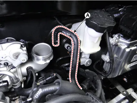
| 12. | Disconnect the brake booster vacuum hose (A).
|
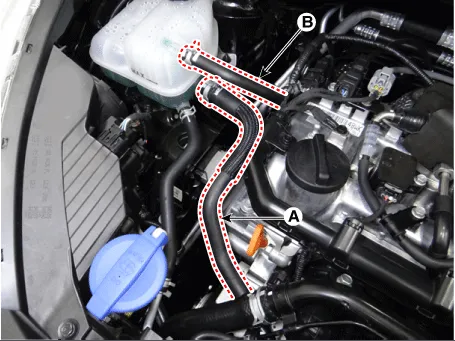
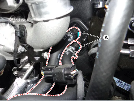
| 13. | Disconnect the recirculation valve (RCV) hose (A) and vacuum hose (B).
|

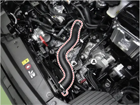
| 14. | Disconnect the heater hoses (A).
|
| 15. | Disconnect the wiring connectors and harness clamps and remove the connector brackets around the engine and transaxle.
|

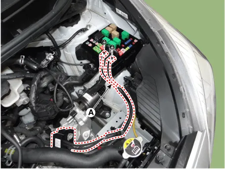
| 16. | Disconnect the fuse box wiring cable (A).
|
| 17. | Remove the transaxle wire harness connectors and control cable from the transaxle.
(Refer to Manual Transaxle System - "Manual transaxle")
|
| 18. | Remove the front muffler.
(Refer to Intake and Exhaust System - "Muffler")
|
| 19. | Remove the roll rod bracket (A).
|
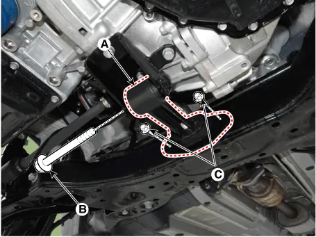
| 20. | Remove the roll rod mounting support bracket (A).
|
| 21. | Remove the sub frame.
(Refer to Suspension system - "Sub frame")
|
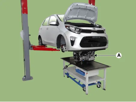
| 22. | Support the engine and transaxle assembly with a lift table. |
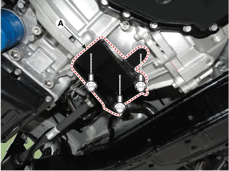
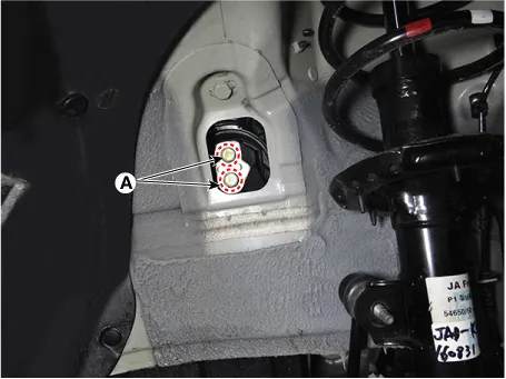
| 23. | Remove the engine mounting bracket (A).
|
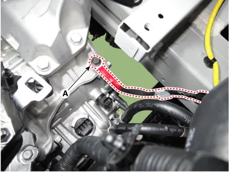
| 24. | Disconnect the transaxle ground cable (A).
|
| 25. | Remove the transaxle side panel packing (A).
|

| 26. | Remove the transaxle mounting bolts (A).
|
| 27. | Remove the engine and transaxle assembly (A) by lifting vehicle.
|
| Installation |
| • | Refill engine with engine oil. |
| • | Refill transaxle with fluid. |
| • | Refill radiator and reservoir tank with engine coolant. |
| • | Clean battery posts and cable terminals with sandpaper. Then, assemble them and apply grease to prevent corrosion. |
| • | Inspect for fuel leakage. |
| – | After
assembling the fuel line, turn on the ignition switch (do not operate
the starter) so that the fuel pump runs for approximately two seconds
and fuel line pressurizes. |
| – | Repeat this operation two or three times, then check for fuel leakage at any point in the fuel line. |
| • | Switch heater control knob to "HOT" position. |
| • | Bleed air from the cooling system. |
| – | Start engine and let it run until it warms up (until the radiator fan operates 3 or 4 times). |
| – | Turn Off the engine. Check the level in the radiator, and add coolant if needed. This will allow trapped air to be released from the cooling system. |
| – | Put radiator cap on tightly, then run the engine again and check for leaks. |
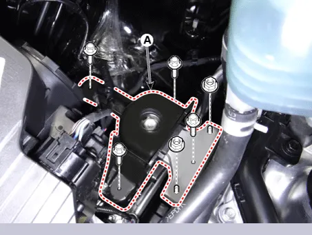
Components and components location Components 1. Engine mounting bracket 2. Roll rod bracket 3. Transaxle mounting bracket Repair procedures Removal and Installation Engine Mounting Bracket 1.
Other information:
Kia Picanto (JA) 2017-2026 Service & Repair Manual: Smart Key Unit
Components and components location Components Connector Pin Information No. Connector A Connector B Connector C 1 - IGN2 Relay_output Battery (+)_Signal 2 SSB Switch1 signal_input P-CAN (Low) - 3 Driver door o
Kia Picanto (JA) 2017-2026 Service & Repair Manual: Blower Motor
Repair procedures Inspection 1. Connect the battery voltage and check the blower motor rotation. 2. If the blower motor voltage is not operated well, substitute with a known-good blower motor and check for proper operation. 3. If the problem is corrected, replace the blower motor.
Categories
- Manuals Home
- Kia Picanto Owners Manual
- Kia Picanto Service Manual
- Normal Condition
- Identification Numbers
- Brake System
- New on site
- Most important about car
