Kia Picanto (JA): Seat Belt Pretensioner / Emergency Fastening Device (EFD)
Description and operation
| Description |
Never
measure resistance of Anchor Pretensioner front-Driver directly,
Current of measuring device may cause unexpected airbag deploy. |

Components and components location
| Components |
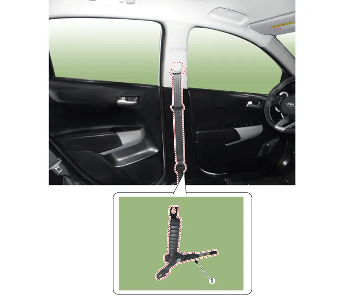
| 1. Emergency Fastening Device (EFD) |
Repair procedures
| Replacement |
| 1. | Disconnect the battery negative cable, and wait for at least thirty seconds before beginning work. |
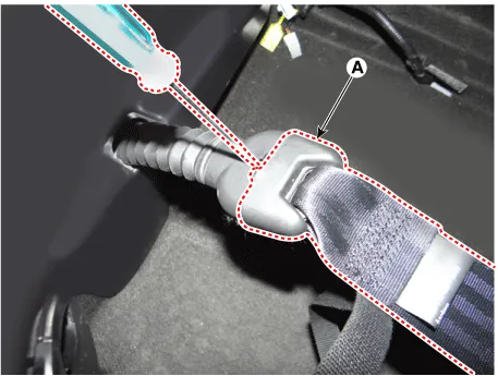
| 2. | Remove the front anchor belt (A).
|
| 3. | Remove the door scuff trim.
(Refer to Body - "Door Scuff Trim")
|
| 4. | Remove the center pillar trim.
(Refer to Body - "Center Pillar Trim")
|
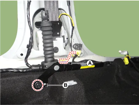
| 5. | Make a gap by pulling the floor carpet. |
| 6. | Disconnect the EFD connector (A). |
| 7. | Remove the EFD mounting bolt (B).
|
| 8. | Install in the reverse order of removal. |
Description and operation Description The Seat Belt Pretensioners (BPT) are installed inside Center Pillar (LH & RH). When a vehicle crashes with a certain degree of frontal impact, the pretensioner seat belt helps to reduce the severity of injury to the front seat occupants by retracting the seat belt webbing.
Components and components location Components Seat Belt Reminder (SBR) Unit 1. Seat Belt Reminder (SBR) Unit Seat Belt Reminder (SBR) Sensnor 1.
Other information:
Kia Picanto (JA) 2017-2026 Service & Repair Manual: Back View Camera System
Components and components location Component Location 1. Back view camera 2. AVN head unit 3. steering angle sensor Description and operation Description 1. To display back of the vehicle to assist the driver, it receives vehicle rearside image signal from the rearview camera and displays it on AVN head unit monitor
Kia Picanto (JA) 2017-2026 Service & Repair Manual: Power Door Locks
Components and components location Component Location 1. Driver power window switch 2. Assist power window switch 3 . Body Comtrol Module (BCM) 4 . Door lock knob 5 . Tailgate actuator 6. Door latch lock actuator 7 . Door lock/unlock switch 8 .
Categories
- Manuals Home
- Kia Picanto Owners Manual
- Kia Picanto Service Manual
- Engine Control / Fuel System
- Front Disc Brake
- Charging System
- New on site
- Most important about car
