Kia Picanto (JA): Evaporative Emission Control System / Canister
Repair procedures
| Removal |
| 1. | Turn the ignition switch OFF and disconnect the battery negative (-) terminal. |
| 2. | Remove the fuel tank assembly.
(Refer to Fuel System - "Fuel Tank")
|
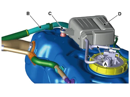
| 3. | Disconnect the vapor (A) and ventilation hose (B). |
| 4. | Remove the mounting bolt (C) and then remove the canister (D).
|
| Installation |
| 1. | Install in the reverse order of removal. |
| Inspection |
| 1. | Check for the following items visually.
A: Canister ↔ Fuel Tank B: Canister ↔ Intake Manifold C: Canister ↔ Atmosphere |

Description and operation Description Evaporative Emission Control System prevents fuel vapor stored in fuel tank from vaporizing into the atmosphere.
Specifications Specification Item Specification Coil Resistance (Ω) 18.
Other information:
Kia Picanto (JA) 2017-2026 Service & Repair Manual: Turn Signal Lamp
Repair procedures Removal Door Mirror Turn Signal Lamp 1. Disconnect the negative (-) battery terminal. 2. Remove the mirror (A) from the mirror holder. Be careful not to damage the fixing clips (A). 3. Disconnect the heating connectors (A) from the mirror.
Kia Picanto (JA) 2017-2026 Service & Repair Manual: Climate Control Air Filtar
Description and operation Description This has particle filter which eliminates foreign materials and odor. The particle filter includes odor filter as well as conventional dust filter to ensure comfortable interior environment. Repair procedures Replacement 1.
Categories
- Manuals Home
- Kia Picanto Owners Manual
- Kia Picanto Service Manual
- Coolant
- Normal Condition
- Engine Control / Fuel System
- New on site
- Most important about car
