Kia Picanto: ISG (Idle Stop & Go) System / Brake switch
Components and components location

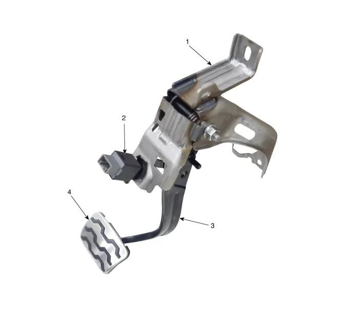
1. Brake member assembly 2. Stop lamp switch
| 3. Brake pedal arm assembly 4. Brake pedal pad
|
Troubleshooting
1. | Part diagnosis
Items
|
Cause
|
Symptom
|
| Switch fuse
| Faulty fuse connection, Damaged fuse
| –
|
Symptom : Shifting gear trouble, Starting failure, Cruise control
function cancelation trouble, EPB function cancelation trouble, Stop
lamp lighting trouble, ESP OFF light illuminated. |
| ①
A waveform inspection is performed using an oscilloscope on each part
during vehicle acceleration/braking. (Refer to stop lamp switch circuit
inspection procedures)
② Refer to the relevant repair procedures
of the part when something abnormal is discovered in the waveform
(Refer to the repair procedures of the relevant part and if necessary
replace it)
| Relay fuse
| Faulty fuse connection, Damaged fuse
| –
| Symptom
: Shifting gear trouble, Starting failure, Cruise control function
cancelation trouble, EPB function cancelation trouble, Stop lamp
lighting trouble , ESP OFF light illuminated. |
| Stop lamp switch
| •
| Damaged wiring of each part |
•
| Faulty connection to connector |
| –
|
Symptom : Shifting gear trouble, Starting failure, Cruise control
function cancelation trouble, EPB function cancelation trouble, Stop
lamp lighting trouble , ESP OFF light illuminated. |
| Stop signal electronic module (If it applies)
| –
| DTC Code : P0504, C2130, C2131 |
–
|
Symptom : Shifting gear trouble, Starting failure, Cruise control
function cancelation trouble, EPB function cancelation trouble, Stop
lamp lighting trouble , ESP OFF light illuminated. |
| Engine control module(ECM)
| –
| Symptom :Shifting gear trouble,Cruise control function cancelation trouble |
| Body control module (BCM)
| | Shift-lock solenoid
| | Inhibitor switch
| –
|
Symptom : Shifting gear trouble, Starting failure, Cruise control
function cancelation trouble, EPB function cancelation trouble |
| Smart Key Unit(SMK)
| | Electronic parking brake
| –
| Symptom : EPB function cancelation trouble , ESP OFF light illuminated. |
| ABS/VDC control module (Pressure sensor)
| –
| Symptom : ESP OFF light illuminated. |
|
|
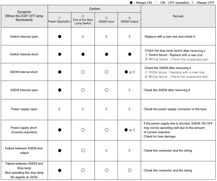
2. | Symptom diagnosis
Symptom
|
Part that could be the cause
|
| Trouble starting
| Switch fuse, Relay fuse, Stop lamp switch, Stop signal electronic module, ABS/VDC control module, Each wire, Connector
| ①
Inspect waveform using an oscilloscope on each part during vehicle
acceleration/braking. (Refer to stop lamp switch circuit inspection
Procedures)
② Refer to the relevant repair procedures of the
part when something abnormal is discovered in the waveform (Refer to the
repair procedures of the relevant part and if necessary replace it)
| Trouble shifting gears
| Switch fuse, Relay fuse, Stop lamp switch, Stop signal electronic module, BCM, ECM, Inhibitor switch, Each wire, Connector
| ESP OFF light illuminated
| Switch fuse, Relay fuse, Stop lamp switch, Stop signal electronic module, ABS/VDC control module, Each wire, Connector
| P0504
| Switch fuse, Relay fuse, Stop lamp switch, Stop signal electronic module, ECM, Each wire, Connector
| Stop lamp not working
| Switch fuse, Relay fuse, Stop lamp switch, Stop signal electronic module, Wire/Connector disconnected
| Stop lamp always turned on
| Stop lamp switch, Stop signal electronic module, Wiring short circuit, Damaged fuse
|
|
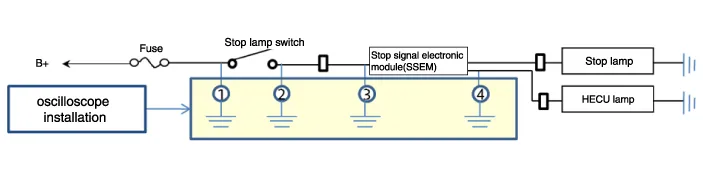
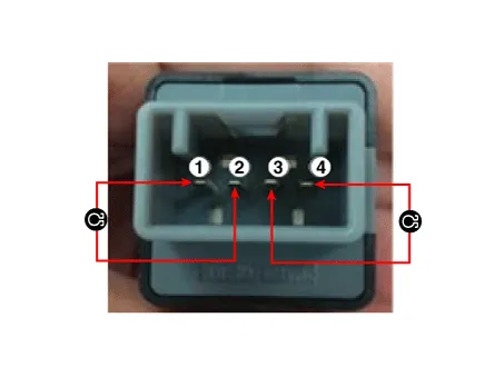
3. | Stop lamp switch system diagnosis

 SSEM : Stop Signal Electronic Module |
4. | Refer to DTC guide when the related DTC codes are displayed. |
Repair procedures
1. | Switch "OFF" ignition and disconnect the negative (-) battery terminal. |
2. | Remove the crash pad lower panel.
(Refer to Body - "Crash Pad Lower Panel")
|
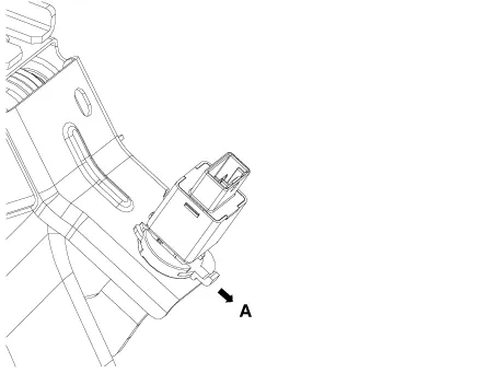
3. | Disconnect the stop lamp switch connector (A).
 |
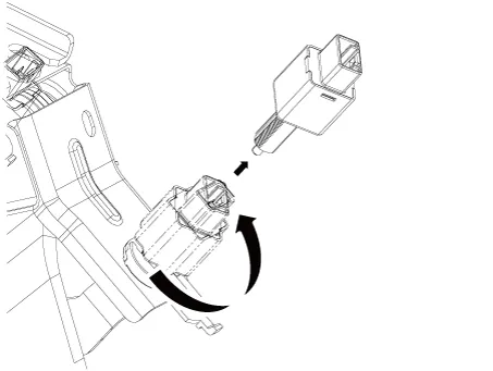
4. | Pull the locking plate (A) as indicated by the
 |
5. | Turn brake switch 45° counterclockwise and remove it.
 |
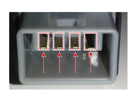
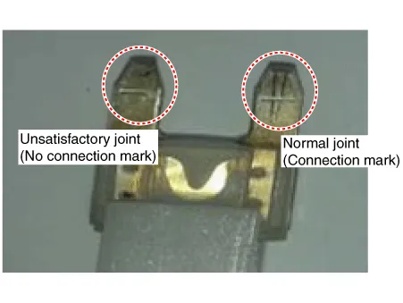
6. | Inspect the removed stop lamp switch according to the below procedures. (1) | Confirm proper connection with terminal part -A confirmation can be made to see if the connector has been secured properly and if a connection mark is present.
 |
(2) | Perform the inspection of parts resistance..

Resistance (Ω)
|
3-4
|
1-2
| Plunger depressed (switch turned OFF)
| Infinite
| 0
| Plunger released (switch turned On)
| 0
| 0
|
|
|
1. | Fix the brake pedal arm and insert the brake switch fully until the contact part is invisible.
 |
2. | After inserting, turn the brake switch 45° clockwise, and then assemble locking plate by pushing it.
 |
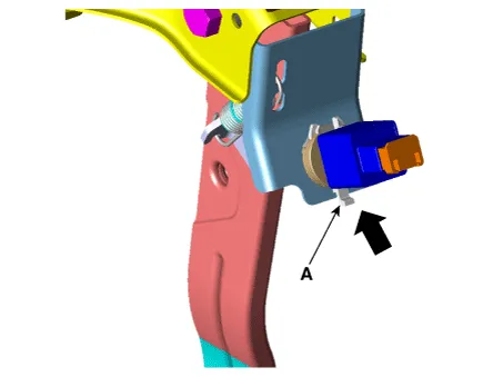
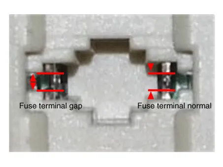
3. | Check the gap (A) between brake switch and bracket.
Stop lamp clearance : 1.0 - 2.0 mm (0.04 - 0.08 in.) |
 If the gap between stop lamp switch and bracket is not 1.0 - 2.0 mm (0.04 - 0.08 in.), perform the above process again. |
|
4. | Install the brake switch connector (A).
 |
1. Fuse inspection
Mount the test fuse to the switch fuse and relay fuse part to confirm a normal joint fit.


2. KDS Data Analysis
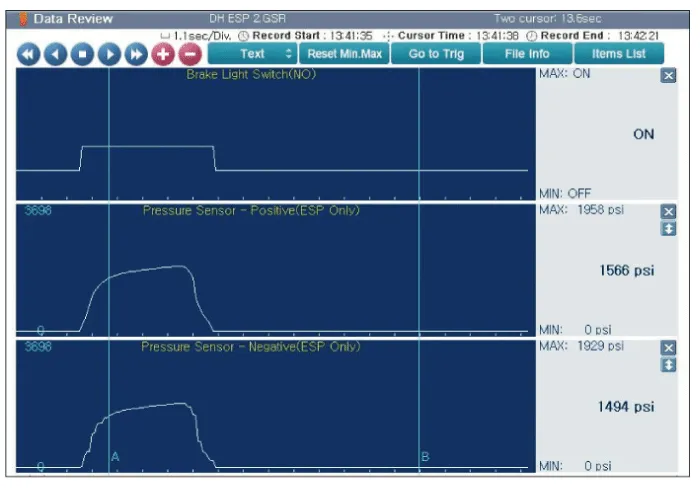
1. | Analyze KDS data and confirm if there is anything wrong with the stop lamp switch. (1) | Connect the KDS to the self-diagnosis connector. |
(2) | Turn the spark switch on |
(3) | Step on the brake pedal. |
(4) | Inspect the "brake switch" category that displays the "sensor data" KDS.)
Normal waveform : The pressure sensor signal value will change according to the brake ON/OFF switch. |
 |
|
3. Inspection of connector by each part
Check to see whether or not each connector has been damaged, or terminal surge, or incomplete connection has taken place
[Engine room junction box]

[ABS/VDC control module]

4. Inspect the stop lamp circuit
Connect probe to each terminal wire and confirm oscilloscope waveform.
[Stop lamp switch input/output]

[Oscilloscope waveform screen]

Specifications
Specification
▷12V, 1.2kW : ISG only
Item
Specification
Rated voltage 12 V, 1.2 kW The number of pinio ...
Description and operation
Description
Via
the seat belt/Door switch, the ISG function can detect that the driver
has fastened the seat belt/door. If the driver has not fastened the seat
be ...
Other information:
The power outlet is designed to provide
power for mobile telephones or other
devices designed to operate with vehicle
electrical systems. The devices
should draw less than 10 amps with
the engine running.
CAUTION
Use the power outlet only when
the engine is running and remove
...
Description and operation
Description
The
starting system consists of the battery, starter, solenoid switch,
ignition switch, inhibitor switch (A/T), clutch pedal switch (M/T),
ignition lock switch, connection wires and the battery cable. When the ignition key is turned to the start posi ...