Kia Picanto (JA): Cooling System / Reservoir Tank
Components and components location
| Components |
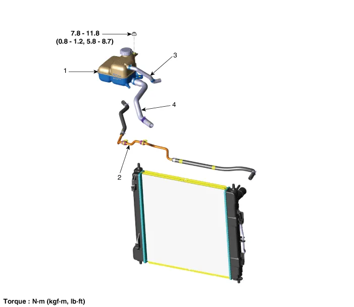
| 1. Reservoir tank 2. Reservoir hose & pipe | 3. Turbo charger water drain hose 4. Water return hose |
Repair procedures
| Removal and Installation |
| 1. | Disconnect the reservoir hose (A), and then drain the coolant from the reservoir tank. |
| 2. | Disconnect the water return hose (B) and turbo charger water drain hose (C).
|

| 3. | Remove the reservoir tank (B).
|

| 4. | Install in the reverse order of removal. |
| 5. | Fill with engine coolant. |
Repair procedures Replacement and air bleeding Never remove the radiator cap when the engine is hot. Serious scalding could be caused by hot fluid under high pressure escaping from the radiator.
Components and components location Components 1. Cooling fan 3. Cooling fan motor 3. Cooling fan shroud Specifications Specifications Item Specification Fan type Puller Fan speed control ON - OFF Air flow rate [㎥/h] 1,570 - 8% min.
Other information:
Kia Picanto (JA) 2017-2026 Service & Repair Manual: Mic
Repair procedures Inspection 1.Disconnect the negative (-) battery terminal. 2.Remove the roof trim assembly. (Refer to Body - "Roof Trim Assembly") 3.Remove the hands free mic (A) after loosening the mounting screws. 4.Check tshe continuity of between terminals.
Kia Picanto (JA) 2017-2026 Service & Repair Manual: High Mounted Stop Lamp
Repair procedures Removal 1. Disconnect the negative (-) battery terminal. 2. Open the tailgate. 3. Loosen the high mounted stop lamp mounting nuts (A). 4. Disconnect the washer nozzle (A) and high mounted stop lamp connector (B). 5. Remove the high mounted stop lamp (C).
Categories
- Manuals Home
- Kia Picanto Owners Manual
- Kia Picanto Service Manual
- Cylinder Head
- Charging System
- Key positions
- New on site
- Most important about car
