Kia Picanto (JA): Power Door Mirrors / Power Door Mirror Actuator
Components and components location
| Components |
| 1. Side repeater lamp |
Repair procedures
| Inspection |
| 1. | Disconnect the negative (-) battery terminal. |
| 2. | Remove the front door quadrant inner cover (A).
|

| 3. | Disconnect the tweeter speaker connector (A).
|

| 4. | Disconnect the power door mirror connector from the harness.
|


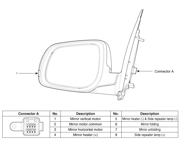
| 5. | Apply battery voltage to each terminal as shown in the table and verify that the mirror operates properly. [Mirror Control (LH/RT)]
[Mirror Heater]
[Side Repeater Lamp]
[Folding Mirror]
|


Components and components location Component Schematic diagrams Circuit Diagram [Folding Mirror Type] [Non-Folding Mirror Type] Repair procedures Inspection 1.
Components and components location Component Location 1. Driver power window switch 2. Assist power window switch 3. Rear power window switch 4.
Other information:
Kia Picanto (JA) 2017-2026 Service & Repair Manual: Body Control Module (BCM)
Specifications Specifications [BCM Type] Items Specifications Rated voltage DC 12 V Operating voltage DC 9 - 16 V Operating temperature -31 - 167°F (-35 - 75°C) Dark current SMK : 3mA / Keyless : 3.
Kia Picanto (JA) 2017-2026 Service & Repair Manual: Sunroof Switch
Components and components location Components Repair procedures Inspection 1. Disconnect the negative (-) battery terminal. 2. Remove the map lamp lens (A). 3. Remove the map lamp (B) after loosening the mounting screws. 4.
Categories
- Manuals Home
- Kia Picanto Owners Manual
- Kia Picanto Service Manual
- Fuel Delivery System
- Clutch Cable
- Coolant
- New on site
- Most important about car
