Kia Picanto (JA): Steering System / Motor Driven Power Steering
Description and operation
| Description |
Components and components location
| Components |
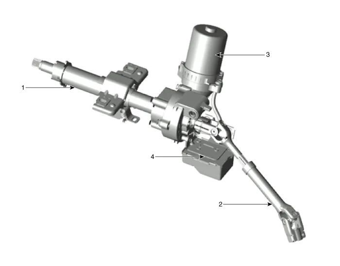
| 1. Steering column 2. Universal joint | 3. MDPS motor 4. MDPS ECU |
Schematic diagrams
| Schematic Diagrams |
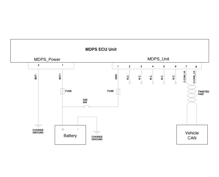
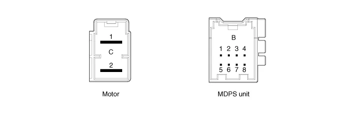
| Harness Connector |
|
Type
|
Pin No
|
Description
|
| Battery | 1 | Battery + |
| 2 | Battery - | |
| VSS | 1 | IGN |
| 2 | - | |
| 3 | - | |
| 4 | - | |
| 5 | - | |
| 6 | - | |
| 7 | HIGH CAN | |
| 8 | LOW CAN |
Repair procedures
| A/S Repair produres |
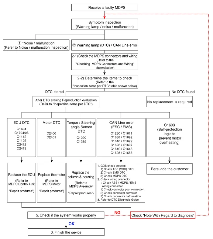
| ① Checking Connectors and Wiring |
| 1. | Checking Connectors and Wiring. Check for damage, push-back, or improper connection in each connector and wiring.
|


| ② Inspection Items per DTC |
|
Item
|
DTC
|
Description
|
Inspection
|
Service action
|
| CAN Line | C1611 | CAN TIME OUT EMS | 1. Check the GDS 2. Check connector tightening. 3. Inspection the ECU CAN connector 4. Check MDPS vehicle grounding status | EMS CAN line inspection |
| C1616 | CAN BUS OFF | Check the chassis can line | ||
| C1622 | Vehicle speed signal error | EMS(Engine ECU) inspection | ||
| Torque sensor | C1290 | Torque sensor signal error | Inspection after DTC clear. Check connector tightening. | Replace column & housing if phenomenon persists |
| C1112 | Torque sensor supply voltage error | Check torque sensor and ECU connection connector. | Replace ECU if phenomenon persists | |
| ECU | C1604 | ECU hardware error | Inspection the ECU connector after Clear DTC | Replace ECU if phenomenon persists |
| ECU | C1705 | EPS Module pre-charge circuit malfunction | Inspection the ECU connector after Clear DTC. | Replace ECU if phenomenon persists |
| Motor | C2400 | Motor signal error | Inspection the Motor connector after Clear DTC. | Replace Motor if phenomenon persists |
| Motor | C2401 | Motor position sensor error | Inspection the Motor connector after Clear DTC. | Replace Motor if phenomenon persists |
| ECU/Motor | C2412 | Motor current error | Inspection the Motor/ECU connector after Clear DTC. | First ECU replacement Replace Motor if phenomenon persists |
| Steering angle sensor | C1259 | Steering Angle sensor error | Steering angle reset after DTC clear Check connector tightening. | Replace column & housing if phenomenon persists |
| Battery | C1102 | Battery voltage low | Check battery voltage status | Battery voltage charging |
| Cooperative control | C1696 | SPAS signal error | SPAS Inspection | Clear DTC. |
| C1697 | ||||
| Cooperative control | C1612 | TCU signal error | TCU Inspection | Clear DTC. |
| C1646 | ||||
| Cooperative control | C1628 | Cluster signal error | Cluster Inspection | Clear DTC. |
| C1656 | ||||
| Cooperative control | C1692 | VSM signal error | VSM Inspection | Clear DTC. |
| C1693 | ||||
| ABS | C1260 | Steering angle signal error | Checking after steering angle reset If the C1259 code does not occur, check the CAN line. | Steering angle reset Clear DTC. |
| Noise / malfunction Repair produres |
| ③ Noise / malfunction Inspection |
|
Symptom
|
Fault description and inspection method
|
Countermeasure
| ||||||
| Noise/rattle | 1. Noise generated near the MDPS column & housing.
|
| ||||||
| Noise/rattle | 1. Check the handle and surrounding fastening parts.
| Check the noise of the relevant part
| ||||||
2. Check where the C-MDPS is installed.
| Check the installation of the cowl | |||||||
3. Check the fastening area of the universal joint bolt.
| Fasten with a new bolt if the universal joint bolt is worn | |||||||
4. Check free playing area of the column when steering while the vehicle is stopped.
| Keep spaces between the surrounding parts
|
| ④ Cautions to be taken while servicing |
| 1. | Failure
occurs due to internal damage because of the drop of and shock and
excessive external force on the new partial component. → Be cautious of shock on the partial component and replace the damaged part (due to drop, etc.) with a new one. |
| 2. | When fastening the steering, excessive impact may result in twisting the center point of the torque sensor. |
| 3. | When removing/installing the connector the wiring may be damaged (deformed) by excessive external force. |
| 4. | Be cautious when storing and replacing the partial components under the abnormal temperature and humidity conditions. |
Description and operation Description The heated steering wheel system improves the thermal comfort of the driver by heating the steering wheel when manually selected.
Repair procedures Replacement 1. Disconnect the battery negative cable. 2. Remove the crash pad lower panel. (Refer to Body - "Crash pad lower panel") 3.
Other information:
Kia Picanto (JA) 2017-2026 Service & Repair Manual: Seat Heater Switch
Components and components location Components 1. Driver side seat heater switch 2. Passenger side seat heater switch Schematic diagrams Circuit Diagram Repair procedures Removal 1. Disconnect the negative (-) battery terminal.
Kia Picanto (JA) 2017-2026 Service & Repair Manual: Smart Key Diagnostic
Repair procedures Inspection Self Diagnosis With Scan Tool It will be able to diagnose defects of SMART KEY system with KDS/GDS quickly. KDS/GDS can operates actuator forcefully, input/output value monitoring and self diagnosis. The following three features will be major problem in SMART KEY system.
Categories
- Manuals Home
- Kia Picanto Owners Manual
- Kia Picanto Service Manual
- Cooling System
- Cylinder Head
- Brake System
- New on site
- Most important about car
