Kia Picanto (JA): Intake And Exhaust System / Intercooler
Components and components location
| Components |
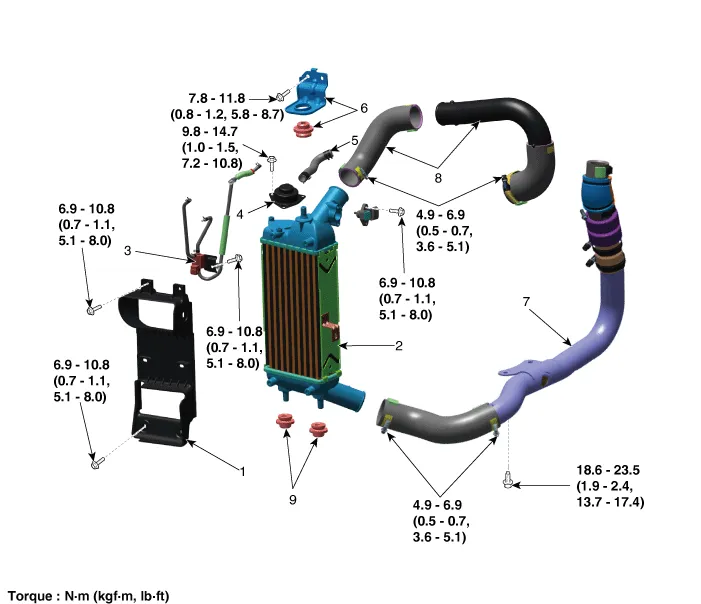
| 1. Intercooler air guard 2. Intercooler 3. Recirculation valve (RCV) control solenoid valve & vacuum hose 4. Recirculation valve (RCV) 5. Recirculation valve (RCV) hose | 6. Intercooler upper mounting bracket & insulator 7. Intercooler inlet hos & pipe 8. Intercooler outlet hos & pipe 9. Intercooler lower mounting insulator |
Repair procedures
| Removal and Installation |
| 1. | Disconnect the negative battery terminal. |
| 2. | Disconnect the intercooler outlet hose & pipe (A)
|

| 3. | Disconnect the recirculation valve (RCV) hose (A) and vacuum hose (B).
|

| 4. | Remove the engine room under cover.
(Refer to Engine and Transaxle Assembly - "Engine Room Under Cover")
|
| 5. | Disconnect the intercooler inlet hose (A)
|

| 6. | Remover the front bumper assembly.
(Refer to body (Interior and Exterior) - "Front Bumper Assembly")
|
| 7. | Remove the headlamps.
(Refer to Body Electrical System - "Head Lamps")
|
| 8. | Disconnect the hood latch.
(Refer to Body (Interior and Exterior) - "Hood Latch")
|
| 9. | Remove the multi-purpose check connector (MPCC) bracket (A).
|

| 10. | Disconnect the reservoir hose clip (A).
|

| 11. | Remove the radiator upper mounting bracket (A).
|

| 12. | Remove the radiator support upper member assembly (A).
|

| 13. | Disconnect the assist emergency braking (AEB) unit connector (A) and horn connector (B).
|

| 14. | Remove the front bumper beam (A).
|

| 15. | Disconnect the boost pressure sensor (BPS) connector (A).
|

| 16. | Disconnect the solenoid valve connector (A).
|

| 17. | Remove the wiring (A) from the intercooler air guard.
|

| 18. | Remove the intercooler air guard (A).
|

| 19. | Remove the intercooler (A).
|

| 20. | Install in the reverse order of removal. |
Components and components location Components 1. Coupler heat protector 2. Warm-up catalytic converter (WCC) 3. Warm-up catalytic converter (WCC) gasket 4.
Components and components location Components 1. Front muffler 2. Catalytic converter & Center muffler assembly 3. Rear muffler 4. Rubber hanger 5.
Other information:
Kia Picanto (JA) 2017-2026 Service & Repair Manual: Multimedia Jack
Schematic diagrams Circuit Diagram Description and operation Description The multimedia jack on the console upper cover is for customers who like to listen to external portable music players like the MP3 etc., through the vehicle's sound system when it is linked to this jack.
Kia Picanto (JA) 2017-2026 Service & Repair Manual: Sunroof Switch
Components and components location Components Repair procedures Inspection 1. Disconnect the negative (-) battery terminal. 2. Remove the map lamp lens (A). 3. Remove the map lamp (B) after loosening the mounting screws. 4.
Categories
- Manuals Home
- Kia Picanto Owners Manual
- Kia Picanto Service Manual
- Brake System
- Charging System
- Fuel Delivery System
- New on site
- Most important about car
