Kia Picanto: Body Electrical System / Ignition Switch Assembly
Kia Picanto JA 2017-2025 Service & Repair Manual / Body Electrical System / Ignition Switch Assembly
Repair procedures
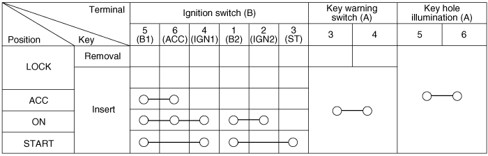
| Inspection |
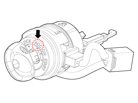
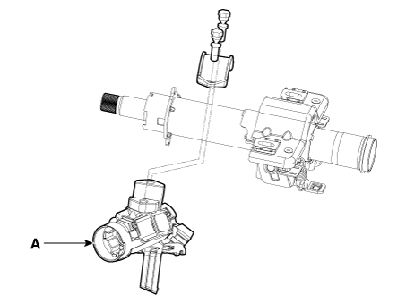
| 1. | Disconnect the key warning switch connector (A) and ignition switch connector (B) from the steering column.
|
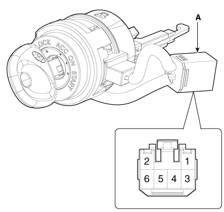
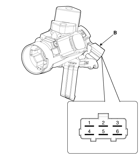
| 2. | Check for continuity between the terminals. |
| 3. | If continuity is not specified, replace the switch.
|
| Removal |
| 1. | Disconnect the negative (-) battery terminal. |
| 2. | Remove the crash pad lower panel.
(Refer to Body - "Crash Pad Lower Panel")
|
| 3. | Remove the steering column upper and lower shroud panel.
(Refer to Body - "Steering Column Shroud Panel")
|
| 4. | Remove the multifunction switch.
(Refer to Body Electrical System - "Multifunction Switch")
|
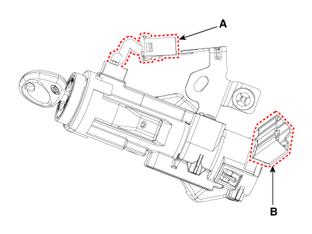
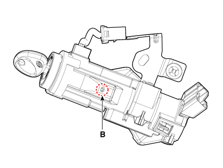
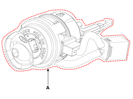
| 5. | Remove the ignition switch connector (A) and key warning / immobilizer connector (B).
|
| 6. | Insert key and turn it to ACC position.
|
| 7. | Pushing lock pin (B) with the awl. |
| 8. | Remove the key lock cylinder (A).
|
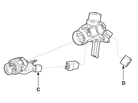
| 9. | Remove the ignition switch (A) after loosening the mounting bolts.
|
| Installation |
|

| 1. | Install the ignition switch. |
| 2. | Install the key lock cylinder. |
| 3. | Connect the ignition switch connector and key warning / immobilizer connector. |
| 4. | Install the multifunction switch. |
| 5. | Install the steering column upper and lower shroud panel. |
| 6. | Install the crash pad lower panel. |
| 7. | Connect the negative (-) battery terminal. |
 Horn
Horn
Components and components location
Component Location
1. Horn switch 2. Horn relay 3. Horn 4. Clock spring
Repair procedures
Removal
1.Disconnect the negative (-) battery ter ...
 Immobilizer System
Schematic diagrams
Circuit Diaram
Description and operation
Description
The
immobilizer system will disable the vehicle unless the proper ignition
key is used, in addition to ...
Other information:
Kia Picanto JA 2017-2025 Service & Repair Manual: Normal Condition
General market Normal Maintenance Schedule - For Gasoline Engine [Except Europe (Including Russia)] The following maintenance services must be performed to ensure good emission control and performance. Keep receipts for all vehicle emission services to protect your warranty. Where both ...
Kia Picanto JA 2017-2025 Service & Repair Manual: Airbag Module Disposal
Description and operation Airbag Disposal Special tool required Deployment tool 0957A-34100A Before scrapping any airbags or side airbags (including those in a whole vehicle to be scrapped), the airbags or side airbags must be deployed. If the vehicle is still within the warranty pe ...
Copyright © www.kpicanto.com 2017-2025
