Kia Picanto (JA): Engine And Transaxle Assembly / Engine Mounting
Components and components location
| Components |
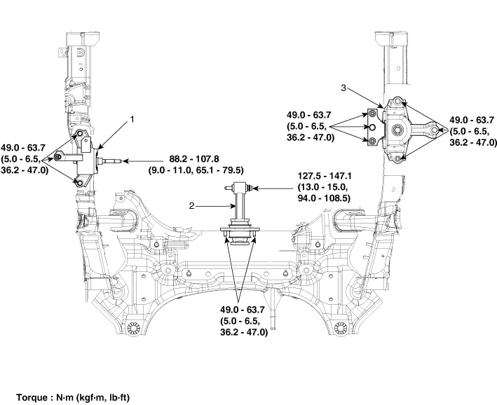
| 1. Engine mounting bracket 2. Roll rod bracket | 3. Transaxle mounting bracket |
Repair procedures
| Removal and Installation |
| 1. | Remove the engine room under cover and RH side cover.
(Refer to Engine and Transaxle Assembly - Engine Room Under Cover")
|
| 2. | Remove the reservoir tank.
(Refer to Cooling System - "Reservoir Tank")
|
| 3. | Install the jack to the edge of upper oil pan to support the engine.
|

| 4. | Remove the engine mounting bracket (A).
|

| 5. | Install in the reverse order of removal. |
| 1. | Remove the engine room under cover.
(Refer to Engine and Transaxle Assembly - "Engine Room Under Cover")
|
| 2. | Remove the intercooler inlet hoses & pipe (A).
|

| 3. | Remove the roll rod bracket (A).
|

| 4. | Install in the reverse order of removal. |
| 1. | Remove the battery and tray.
(Refer to Engine Electrical System - "Battery")
|
| 2. | Remove the engine room under cover and LH side cover.
(Refer to Engine and Transaxle Assembly - Engine Room Under Cover")
|
| 3. | Install the jack to the edge of transaxle. |
| 4. | Remove the transaxle side panel packing (A).
|

| 5. | Remove the transaxle mounting bolts (A).
|

| 6. | Remove the transaxle mounting bracket (A).
|

| 7. | Install in the reverse order of removal. |
Repair procedures Removal and Installation Engine Room Under Cover 1. Remove the engine room under cover (A). Tightening torque : 7.
Repair procedures Removal • Use fender covers to avoid damaging painted surfaces. • To avoid damage, unplug the wiring connectors carefully while holding the connector portion.
Other information:
Kia Picanto (JA) 2017-2026 Service & Repair Manual: Headlamps
Description and operation Description BI-FUNCTION 1. Definition – A headlamp with integrated functions of high and low beam – The light is controlled by rotating the shield inserted to the lens.
Kia Picanto (JA) 2017-2026 Service & Repair Manual: Power Door Locks
Components and components location Component Location 1. Driver power window switch 2. Assist power window switch 3 . Body Comtrol Module (BCM) 4 . Door lock knob 5 . Tailgate actuator 6. Door latch lock actuator 7 . Door lock/unlock switch 8 .
Categories
- Manuals Home
- Kia Picanto Owners Manual
- Kia Picanto Service Manual
- Brake System
- General Information
- Body Electrical System
- New on site
- Most important about car
