Kia Picanto (JA): Engine Control / Fuel System
Specifications
Items
|
Specification
|
Fuel Tank
| Capacity
| 35 L (9.2 U.S. gal, 37.0 U.S. qt, 30.8 lmp.qt.)
|
Fuel Filter
| Type
| Paper type
|
Fuel Pressure
| Low Pressure Fuel Line
| 480 - 520 kPa (4.9 - 5.3 kgf/cm² , 69.6 - 75.4 psi)
|
High Pressure Fuel Line
| 2 - 20 MPa ( 20.4 - 203.9 kgf/cm² , 290.1 - 2900.8 psi)
|
Fuel Pump
| Type
| Electrical, in-tank type
|
Driven by
| Electric motor
|
High Pressure Fuel Pump
| Type
| Mechanical type
|
Driven by
| Camshaft
|
Throttle Position Sensor (TPS) [integrated into ETC module]
Item
|
Opening Percentage (%)
|
Output Voltage (V) [Vref = 5V]
|
TPS1
| C.T
| 8.5 - 11.5
| 0.43 - 0.58
|
W.O.T
| 88 - 96
| 4.40 - 4.80
|
TPS2
| C.T
| 88.5 - 91.5
| 4.43 - 4.58
|
W.O.T
| 2 - 10
| 0.10 - 0.50
|
Fail Safe
| Throttle valve stuck at 5°
|
Supply Voltage (V)
| 4.8 - 5.2
|
Type
| Hall IC Non-contact sensor [Integrated into ETC Module]
|
Manifold Absolute Pressure Sensor (MAPS)
▷ Type: Piezo-resistive pressure sensor type
Pressure
[kPa (kgf/cm², psi)]
|
Output Voltage (V) [Vref = 5V]
|
32.5 (0.33, 4.71)
| 0.5
|
284 (2.90, 41.19)
| 4.5
|
Intake Air Temperature Sensor (IATS)
▷ Type: Thermistor type
Temperature
|
Resistance (kΩ)
|
°C
|
°F
|
-40
| -40
| 40.93 - 48.35
|
-30
| -22
| 23.43 - 27.34
|
-20
| -4
| 13.89 - 16.03
|
-10
| 14
| 8.5 - 9.7
|
0
| 32
| 5.38 - 6.09
|
10
| 50
| 3.48 - 3.90
|
20
| 68
| 2.31 - 2.57
|
30
| 86
| 1.9 - 2.1
|
40
| 104
| 1.08 - 1.21
|
50
| 122
| 0.76 - 0.85
|
60
| 140
| 0.54 - 0.62
|
70
| 158
| 0.40 - 0.45
|
80
| 176
| 0.29 - 0.34
|
90
| 194
| 0.22 - 0.26
|
100
| 212
| 0.17 - 0.20
|
110
| 230
| 0.13 - 0.15
|
120
| 248
| 0.10 - 0.12
|
130
| 266
| 0.08 - 0.09
|
Ambient Temperature Sensor(ATS)
▷Type : Thermistor type
Temperature[⁰C(⁰F)]
|
Resistance(kΩ)
|
-40(-40)
| 811.1 - 956.8
|
-20(-4)
| 255.6 - 287.7
|
0(32)
| 91.5 - 98.8
|
20(68)
| 36.6 - 38.0
|
30(86)
| 23.8 - 24.7
|
40(104)
| 15.7 - 16.6
|
50(122)
| 10.6 - 11.3
|
60(140)
| 7.2 - 7.9
|
80(176)
| 3.6 - 4.0
|
Boost Pressure Sensor (BPS)
Pressure
[kPa (kgf/cm², psi)]
|
Output Voltage (V) [Vref = 5V]
|
32.5 (0.33, 4.71)
| 0.5
|
284 (2.90, 41.19)
| 4.5
|
▷ Type: Piezo-resistive pressure sensor type
Engine Coolant Temperature Sensor (ECTS)
▷ Type: Thermistor type
Temperature
|
Resistance (kΩ)
|
°C
|
°F
|
-40
| -40
| 48.14
|
-20
| -4
| 14.13 - 16.83
|
0
| 32
| 5.79
|
20
| 68
| 2.31 - 2.59
|
40
| 104
| 1.15
|
60
| 140
| 0.59
|
80
| 176
| 0.32
|
100
| 212
| 0.19
|
110
| 230
| 0.145 - 0.149
|
120
| 248
| 0.12
|
Crankshaft Position Sensor (CKPS)
NON- ISG
Item
|
Specification
|
Type
| Magnetic field sensitive type
|
Coil Resistance (Ω)
| 819 - 1001 [20°C (68°F)]
|
Pin
| 2
|
ISG only
Item
|
Specification
|
Type
| Hall effect type
|
Air Gap (mm)
| 0.5 - 1.5
|
Pin
| 3
|
Camshaft Position Sensor (CMPS)
Item
|
Specification
|
Type
| Hall effect type
|
Air Gap (mm)
| 0.5 - 1.5
|
Pin
| 3
|
Knock Sensor (KS)
Item
|
Specification
|
Resistance(MΩ)
| 4.87
|
Capacitance (pF)
| 850 - 1150
|
Type
| Piezo-electricity
|
Pin
| 2
|
Heated Oxygen Sensor (HO2S)
HO2S [Bank 1/Sensor 1]
Item
|
Specification
|
Heater Resistance (Ω)
| 2.5 - 4.0 [20°C(68°F)]
|
Type
| Linear
|
Pin
| 6
|
HO2S [Bank 1/Sensor 2]
Item
|
Specification
|
Heater Resistance (Ω)
| Approximately 9.0 [20°C(68°F)]
|
Type
| Binary
|
Pin
| 4
|
Rail Pressure Sensor (RPS)
Item
|
Specification
|
Rated Voltage (V)
| 5
|
Operating Voltage (V)
| 4.75 - 5.25
|
Connector
| 3
|
Pressure
|
Output Voltage (V) [Vref=5V]
|
bar
|
[MPa (kgf/cm², psi)]
|
0
| 0 (0, 0)
| 0.5
|
175
| 14 (142, 2031)
| 2.5
|
350
| 28 (286, 4061)
| 4.5
|
Accelerator Position Sensor (APS)
Accelerator
Position
|
Output Voltage (V) [Vref = 5V]
|
APS1
|
APS2
|
C.T
| 0.7 - 0.8
| 0.32 - 0.42
|
W.O.T
| 3.98 - 4.22
| 1.93 - 2.17
|
Electric WGT Control Actuator Sensor [integrated into EWGA]
Item
|
Specification
|
Supply Voltage (V)
| 4 -6
|
DC Motor [integrated into ETC module]
Item
|
Specification
|
Coil Resistance (Ω)
| 0.3 - 100 [20°C(68°F)]
|
Maximum Allowable Current (A)
| < 10.0
|
Type
| DC Motor [Integrated into ETC Module]
|
Injector
Item
|
Specification
|
Coil Resistance (Ω)
| 1.43 - 1.57 (23°C)
|
Fuel Pressure
| bar
| 200 - 267
|
MPa
| 20.0 - 26.7
|
kgf/cm²
| 203 - 2722.6
|
psi
| 2900 - 3872.5
|
Pin
| 2
|
Purge Control Solenoid Valve (PCSV)
Item
|
Specification
|
Coil Resistance (Ω)
| 18.5 - 22.5 [23°C(73.4°F)]
|
Pin
| 2
|
CVVT Oil Control Valve (OCV)
Item
|
Specification
|
Coil Resistance (Ω)
| 6.9 - 7.9 [20°C(68°F)]
|
Control Current (mA)
| 100 - 1000
|
Reted Voltage (V)
| 12
|
Insulation resistance (MΩ)
| 50 [DC 500 V/1 Min]
|
Pin
| 2
|
Electric WGT Control Actuator DC Motor [integrated into EWGA]
Item
|
Specification
|
Max Current (A)
| < 6.0
|
Coil Resistance (Ω)
| 2.4 ± 0.36
|
Supply Voltage (V)
| 13.5
|
Supply Voltage Range (V)
| 9 - 16
|
Operating Frequency (kHz)
| 0.9 - 1.1
|
RCV Control Solenoid Valve
Item
|
Specification
|
Coil Resistance(Ω)
| 28.3-31.1 [20°C(68°F)]
|
Pin
| 2
|
Fuel Pressure Control Valve (FPCV)
Item
|
Specification
|
Coil Resistance (Ω)
| 0.54 [20°C(68°F)]
|
Pin
| 2
|
Peak Current (A)
| 5.3
|
Holding Current (A)
| 2.68
|
High Pressure Fuel Pressure
| bar
| 20 - 200
|
MPa
| 2 - 20
|
kgf/cm²
| 20.4 - 203.9
|
psi
| 290.1 - 2900.8
|
Item
|
Specification
|
Ignition Timing (°)
| BTDC 0° ± 10°
|
Idle Speed (rpm)
| A/C OFF
(Neutral, N, P-range)
| 850 ± 100
|
A/C ON
| 850 ± 100
|
Item
|
kgf·m
|
N·m
|
lb·ft
|
ECM bracket mounting bolt / nut
| 1.0 - 1.2
| 9.8 - 11.8
| 7.2 - 8.7
|
ECM mounting nut
| 1.0 - 1.2
| 9.8 - 11.8
| 7.2 - 8.7
|
Electronic Throttle Control (ETC) moule mounting bolt
| 0.8 - 1.0
| 7.8 - 9.8
| 5.7 - 7.2
|
Manifold Absolute Pressure Sensor (MAPS) mounting screw
| 0.65 - 0.85
| 6.4 - 8.3
| 4.7 - 6.1
|
Intake Air Temperature Sensor (IATS) mounting screw
| 0.65 - 0.85
| 6.4 - 8.3
| 4.7 - 6.1
|
Boost Pressure Sensor (BPS) mounting bolt
| 0.8 - 1.2
| 7.8 - 11.7
| 5.7 - 8.6
|
Engine Coolant Temperature Sensor (ECTS)
| 2.0 - 4.0
| 19.6 - 39.2
| 14.4 - 28.9
|
Crankshaft Position Sensor (CKPS) mounting bolt
| 1.0 - 1.2
| 9.8 - 11.8
| 7.2 - 8.7
|
Camshaft Position Sensor (CMPS) [Bank 1 / Intake] mounting bolt
| 1.0 - 1.2
| 9.8 - 11.8
| 7.2 - 8.7
|
Camshaft Position Sensor (CMPS) [Bank 1 / Exhaust] mounting bolt
| 1.0 - 1.2
| 9.8 - 11.8
| 7.2 - 8.7
|
Knock Sensor (KS) mounting bolt
| 1.9 - 2.4
| 18.6 - 23.5
| 13.7 - 17.3
|
Heated Oxygen Sensor (HO2S) [Bank 1 / sensor 1]
| 4.0 - 5.0
| 39.2 - 49.1
| 28.9 - 36.2
|
Heated Oxygen Sensor (HO2S) [Bank 1 / sensor 2]
| 4.0 - 5.0
| 39.2 - 49.1
| 28.9 - 36.2
|
Rail Pressure Sensor (RPS)
| 3.1 - 4.1
| 30.0 - 35.0
| 22.1 - 29.5
|
Accelerator Pedal Position Sensor (APS) mounting nut
[APS integrated into Accelerator pedal module]
| 1.3 - 1.6
| 12.7 - 15.7
| 9.4 - 11.6
|
Purge Control Solenoid Valve (PCSV) bracket mounting bolt
| 1.0 - 1.2
| 9.8 - 11.8
| 7.2 - 8.7
|
CVVT Oil Control Valve (OCV) [Bank 1 / Intake] mounting bolt
| 1.0 - 1.2
| 9.8 - 11.8
| 7.2 - 8.7
|
CVVT Oil Control Valve (OCV) [Bank 1 / Exhaust] mounting bolt
| 1.0 - 1.2
| 9.8 - 11.8
| 7.2 - 8.7
|
Electric Waste Gate Actuator (EWGA) mounting bolt
| 0.6 - 0.8
| 6.0 - 8.0
| 4.4 - 5.9
|
RCV control solenoid valve bracket mounting bolt
| 1.0 - 1.2
| 9.8 - 11.8
| 7.2 - 8.7
|
Item
|
kgf·m
|
N·m
|
lb·ft
|
Fuel tank mounting nut
| 4.0 - 5.5
| 39.2 - 54.0
| 28.9 - 39.8
|
Fuel pump plate cover mounting bolt
| 0.2 - 0.3
| 2.0 - 2.9
| 1.4 - 2.2
|
Filler - neck assembly mounting bolt
| 0.8 - 1.2
| 7.8 - 11.8
| 5.8 - 8.7
|
Filler - neck assembly bracket mounting bolt
| 0.8 - 1.2
| 7.8 - 11.8
| 5.8 - 8.7
|
Delivery pipe & injector assembly mounting bolt
| 1.9 - 2.4
| 18.6 - 23.5
| 13.7 - 17.4
|
High pressure fuel pipe flange nut
| 2.7 - 3.3
| 26.5 - 32.4
| 9.5 - 23.9
|
High pressure fuel pipe function block mounting bolt
| 1.0 - 1.2
| 9.8 - 11.8
| 7.2 - 8.7
|
High pressure fuel pump mounting bolt
| 1.3 - 1.5
| 12.8 - 14.7
| 9.4 - 10.9
|
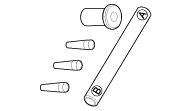
Special service tools
Tool Name / Number
|
Illustration
|
Description
|
Fuel pressure gauge
09353-24100
|
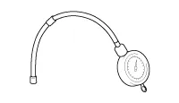 | Used for measuring the pressure in fuel line
|
Fuel pressure gauge adapter
0K353-D4100
|
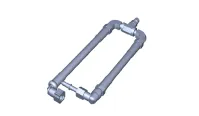 | Used for connecting between high pressure fuel pump and low pressure fuel feed tube to measure the pressure in fuel line
|
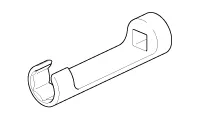
Heated oxygen sensor socket wrench
09392-1Y100
|
 | Used for removing / installing heated oxygen sensor
※SST 09392-2H100 also can be used
|
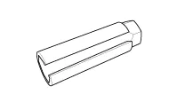
Torque wrench socket
09314-3Q100 or 09314-27130(19mm)
|
 | Used for removing / installing high pressure fuel pipe
|
Injector combustion seal guide & sizing tool
09353-2B000
|
 | Used for installing injector combustion seal on injector
|
Troubleshooting
Basic Troubleshooting Guide
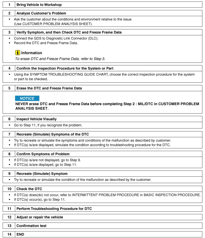
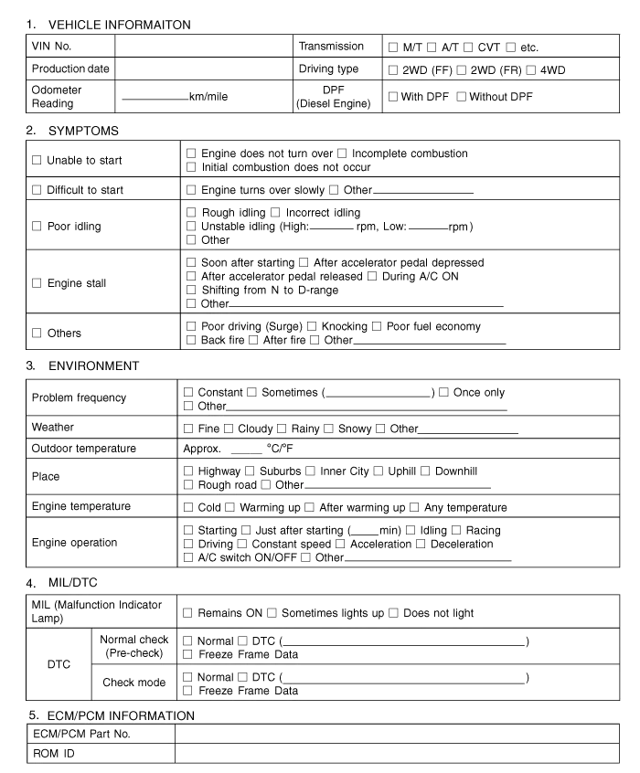
Customer Problem Analysis Sheet
Basic Inspection Procedure
Measuring Condition of Electronic Parts' Resistance
The
measured resistance at high temperature after vehicle running may be
high or low. So all resistance must be measured at ambient temperature
(20°C, 68°F), unless stated otherwise.
| •
| The resistance measured outside the ambient temperature (20°C, 68°F) is the reference value. |
|
Intermittent Problem Inspection Procedure
Sometimes
the most difficult case in troubleshooting is when a problem symptom
occurs but does not recur when tested. An example would be if a problem
appears only when the vehicle is cold but has not appeared when warm.
In this case, the technician should thoroughly make out a "Customer
Problem Analysis Sheet" and recreate (simulate) the environment and
condition in which the vehicle was having the issue.
| 1. | Clear Diagnostic Trouble Code (DTC). |
| 2. | Inspect
connector connection, and check terminal for poor connections, loose
wires, bent, broken or corroded pins, and then verify that the
connectors are always securely fastened.
 |
| 3. | Slightly shake the connector and wiring harness vertically and horizontally. |
| 4. | Repair or replace the component with a problem. |
| 5. | Perform road test to verify that the problem has disappeared. |
● Simulating Vibration
| a. | Sensors and Actuators : Slightly vibrate sensors, actuators or relays by finger. | •
| Strong vibration may break sensors, actuators or relays |
|
|
| b. | Connectors and Harness : Lightly shake the connector and wiring harness vertically and then horizontally. |
● Simulating Heat
| a. | Heat components suspected of causing the malfunction with a hair dryer or other heat source. | •
| DO NOT heat components to the point where they may be damaged. |
| •
| DO NOT heat the ECM directly. |
|
|
● Simulating Water Sprinkling
| a. | Sprinkle water onto vehicle to simulate a rainy day or a high humidity condition. | •
| DO NOT sprinkle water directly onto the engine compartment or electronic components. |
|
|
● Simulating Electrical Load
| a. | Turn on all electrical systems to simulate excessive electrical loads (Radios, fans, lights, rear window defogger, etc.). |
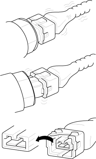
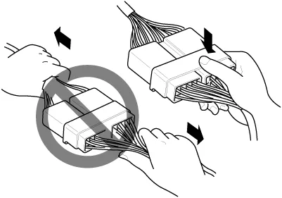
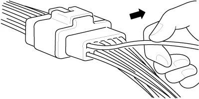
Connector Inspection Procedure
| 1. | Handling of Connector | a. | Never pull on the wiring harness when disconnecting connectors.
 |
| b. | When removing the connector with a lock, press or pull locking lever.
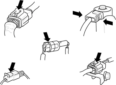 |
| c. | Listen for a click when locking connectors. This sound indicates that they are securely locked.
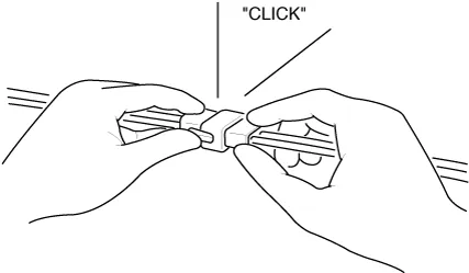 |
| d. | When a tester is used to check for continuity, or to measure voltage, always insert tester probe from wire harness side.
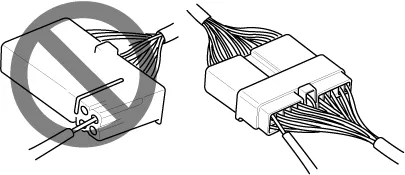 |
| e. | Check waterproof connector terminals from the connector side. Waterproof connectors cannot be accessed from harness side.
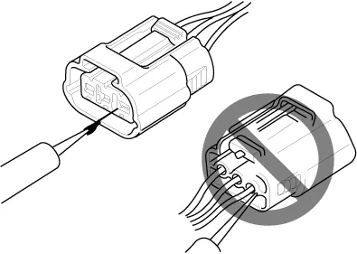 | •
| Use a fine wire to prevent damage to the terminal. |
| •
| Do not damage the terminal when inserting the tester lead. |
|
|
|
| 2. | Checking Point for Connector | a. | While the connector is connected: Hold the connector, check connecting condition and locking efficiency. |
| b. | When the connector is disconnected: Check missed terminal, crimped terminal or broken core wire by slightly pulling the wire harness. Visually check for rust, contamination, deformation and bend. |
| c. | Check terminal tightening condition: Insert a spare male terminal into a female terminal, and then check terminal tightening conditions. |
| d. | Lightly pull on each wire to ensure that all wires are secured in the terminal.
 |
|
| 3. | Repairing Connector Terminal | a. | Clean the contact points using air gun and/or shop rag. | •
| Never use sand paper when polishing the contact points, otherwise the contact point may be damaged. |
|
|
| b. | In case of abnormal contact pressure, replace the female terminal. |
|
Wire Harness Inspection Procedure
| 1. | Before removing the wire harness, check the wire harness position and crimping in order to restore it correctly. |
| 2. | Check for twisted, pulled or loose wire harness. |
| 3. | Check for abnormally high temperature of wire harness. |
| 4. | Check if the wire harness is rotating, moving or vibrating against the sharp edge of a part. |
| 5. | Check the connection between the wire harness and any installed part. |
| 6. | If the covering of wire harness is damaged; secure, repair or replace the harness. |
Electrical Circuit Inspection Procedure
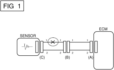
● Check Open Circuit
| 1. | Procedures for Open Circuit If
an open circuit occurs (as seen in [FIG. 1]), it can be found by
performing Step 2 (Continuity Check Method) or Step 3 (Voltage Check
Method) as shown below.
 |
| 2. | Continuity Check Method | •
| When measuring the resistance, lightly shake the wire harness vertically or horizontally. |
|
Specification (Resistance)
1Ω or less → Normal Circuit 1MΩ or Higher → Open Circuit |
| a. | Disconnect connectors (A) and (C) and measure resistance between connectors (A) and (C) as shown in [FIG. 2]. In
[FIG. 2], the measured resistance is higher than 1MΩ for line 1 and
lower than 1Ω for line 2. Specifically, the open circuit is in line 1.
(Line 2 is normal.) To find exact breaking point, check sub line of line
1 as described in the following step.
 |
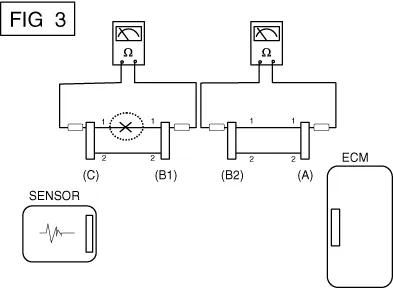
| b. | Disconnect
the connector (B), and measure the resistance between connectors (C)
and (B1) and between (B2) and (A) as shown in [FIG. 3]. In
this case, the measured resistance between connectors (C) and (B1) is
higher than 1MΩ and the open circuit is between terminal 1 of connector
(C) and terminal 1 of connector (B1).
 |
|
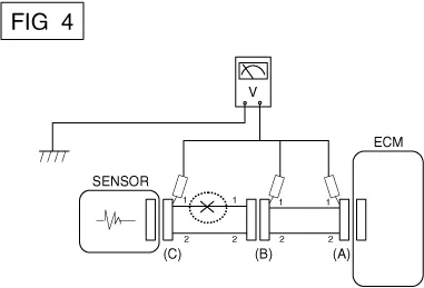
| 3. | Voltage Check Method | a. | With
each connector still connected, measure the voltage between the chassis
ground and terminal 1 of each of connectors (A), (B) and (C) as shown
in [FIG. 4]. The measured voltage of each connector is 5V, 5V and 0V respectively. So the open circuit is between connector (C) and (B).
 |
|
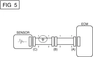
● Check Short Circuit
| 1. | Test Method for Short to Ground Circuit | •
| Continuity Check with Chassis Ground |
If
short to ground circuit occurs as shown in [FIG. 5], the broken point
can be found by performing Step 2 (Continuity Check Method with
Chassis Ground) as shown below.
 |
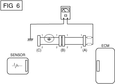
| 2. | Continuity Check Method (with Chassis Ground) | •
| Lightly shake the wire harness vertically or horizontally when measuring the resistance. |
|
Specification (Resistance)
1Ω or less → Short to Ground Circuit 1MΩ or Higher → Normal Circuit |
| a. | Disconnect connectors (A) and (C) and measure the resistance between connector (A) and Chassis Ground as shown in [FIG. 6]. The
measured resistance is below 1 Ω for line 1 and higher than 1 MΩ for
line 2. Specifically, the short to ground circuit is in line 1. (Line 2
is normal.) To find exact broken point, check the sub line of line 1 as
described in the following step.
 |
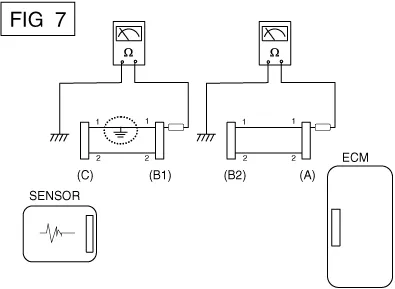
| b. | Disconnect
connector (B), and measure the resistance between connector (A) and
chassis ground, and between (B1) and chassis ground as shown in [FIG.
7]. The measured resistance between connector (B1)
and chassis ground is 1Ω or less. The short to ground circuit is between
terminal 1 of connector (C) and terminal 1 of connector (B1).
 |
|
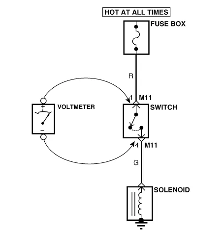
● Testing For Voltage Drop
This test checks for voltage drop along a wire, or through a connection orswitch.
| A. | Connect
the positive lead of a voltmeter to the end of the wire (or to the side
of the connector or switch) closest to the battery. |
| B. | Connect the negative lead to the other end of the wire. (or the other side of the connector or switch) |
| D. | The
voltmeter will show the difference in voltage between the two points. A
difference, or drop of more than 0.1 volts (50mV in 5V circuits), may
indicate a problem. Check the circuit for loose or dirty connections. |
Symptom Troubleshooting Guide Chart
Main symptom
|
Diagnostic procedure
|
Also check for
|
Unable to start
(Engine does not turn over)
| | 1) | Test the battery.
(Refer to Engine Electrical System - "Battery")
|
| 2) | Test the starter.
(Refer to Engine Electrical System - "Starter")
|
| 3) | Clutch start switch (M/T) |
|
|
Unable to start
(Incomplete combustion)
| | 1) | Test the battery.
(Refer to Engine Electrical System - "Battery")
|
| 2) | Check the fuel pressure |
| 3) | Check the ignition circuit.
(Refer to Engine Electrical System - "Ignition System")
|
| 4) | Troubleshoot the immobilizer system.
(Refer to Body Electrical System - "Immobilizer System")
(In case immobilizer lamp flashes) |
| | •
| Slipped or broken timing belt |
|
Difficult to start
| | 1) | Test the battery.
(Refer to Engine Electrical System - "Battery")
|
| 2) | Check the fuel pressure |
| 3) | Check the ECT sensor and circuit (Check DTC) |
| 4) | Check the ignition circuit.
(Refer to Engine Electrical System - "Ignition System")
|
| |
Poor idling
(Rough, unstable or incorrect Idle)
| | 1) | Check the fuel pressure. |
| 2) | Check the Injector.
(Refer to Engine Control System - "Injector")
|
| 3) | Check the long term fuel trim and short term fuel trim (Refer to CUSTOMER DATASTREAM) |
| 4) | Check the idle speed control circuit (Check DTC) |
| 5) | Inspect and test the Throttle Body |
| 6) | Check the ECT sensor and circuit (Check DTC) |
| |
Engine stall
| | 1) | Test the battery.
(Refer to Engine Electrical System - "Battery")
|
| 2) | Check the fuel pressure.
(Refer to Fuel Delivery System - "Fuel Pressure Test")
|
| 3) | Check the idle speed control circuit (Check DTC) |
| 4) | Check the ignition circuit.
(Refer to Engine Electrical System - "Ignition System")
|
| 5) | Check the CKPS Circuit (Check DTC) |
| |
Poor driving
(Surge)
| | 1) | Check the fuel pressure.
(Refer to Fuel Delivery System - "Fuel Pressure Test")
|
| 2) | Inspect and test Throttle Body |
| 3) | Check the ignition circuit.
(Refer to Engine Electrical System - "Ignition System")
|
| 4) | Check the ECT Sensor and Circuit (Check DTC) |
| 5) | Test the exhaust system for a possible restriction.
(Refer to Engine Mechanical System - "Turbo Charger & Exhaust Manifold")
|
| 6) | Check the long term fuel trim and short term fuel trim (Refer to CUSTOMER DATASTREAM) |
| |
Knocking
| | 1) | Check the fuel pressure.
(Refer to Delivery System - "Release Residual Pressure in Fuel Line”)
|
| 2) | Inspect the engine coolant.
(Engine Mechanical System - "Radiator")
|
| 3) | Inspect the radiator and the electric cooling fan.
(Engine Mechanical System - "Radiator")
|
| 4) | Check the spark plugs.
(Refer to Engine Electrical System - "Ignition System")
|
| |
Poor fuel economy
| | 1) | Check customer's driving habits · A/C on full time or the defroster mode on? · Are tires at correct pressure? · Is excessively heavy load being carried? · Is acceleration too much, too often? |
| 2) | Check the fuel pressure.
(Refer to Delivery System - "Release Residual Pressure in Fuel Line”)
|
| 3) | Check the injector.
(Refer to Engine Control System - "Injector")
|
| 4) | Test the exhaust system for a possible restriction |
| 5) | Check the ECT sensor and circuit |
| |
Hard to refuel
(Overflow during refueling)
| | 1) | Inspect the fuel filler hose/pipe · Pinched, kinked or blocked? · Filler hose is torn |
| 2) | Inspect the fuel tank vapor vent hose between the EVAP. canister and air filter |
| 3) | Check the EVAP. canister |
| | •
| Malfunctioning gas station filling nozzle (If this problem occurs at a specific gas station during refueling) |
|
Description and operation
Description
Continuous
Variable Valve Timing (CVVT) system advances or retards the valve
timing of the intake and exhaust valves in accordance with the ECM
control signal calculated by the engine speed and load.
Components and components location
Components Location
1. ECM (Engine Control Module) 2. Manifold Absolute Pressure Sensor (MAPS) 3. Intake Air Temperature Sensor (IATS) 4.
Other information:
Schematic diagrams
Circuit Diagram
Description and operation
Description
The
multimedia jack on the console upper cover is for customers who like to
listen to external portable music players like the MP3 etc., through
the vehicle's sound system when it is linked to this jack.
C


