Kia Picanto (JA): Your vehicle at a glance / Engine compartment
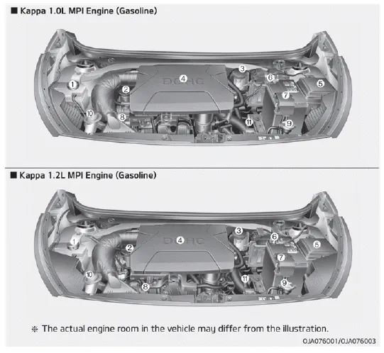
1. Engine coolant reservoir
2. Engine oil filler cap
3. Brake / clutch fluid reservoir
4. Air cleaner
5. Fuse box
6. Negative battery terminal
7. Positive battery terminal
8. Engine oil dipstick
9. Radiator cap
10. Windshield washer fluid reservoir
11. Automatic transaxle fluid dipstick
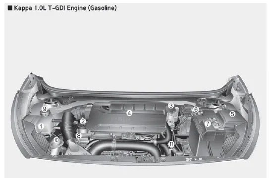
1. Engine coolant reservoir
2. Engine oil filler cap
3. Brake / clutch fluid reservoir
4. Air cleaner
5. Fuse box
6. Negative battery terminal
7. Positive battery terminal
8. Engine oil dipstick
9. Radiator cap
10. Windshield washer fluid reservoir
11. Automatic transaxle fluid dipstick
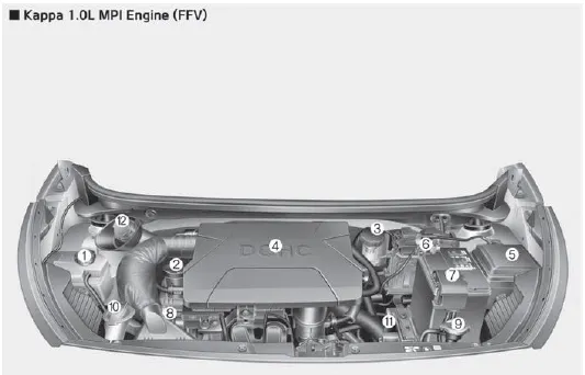
1. Engine coolant reservoir
2. Engine oil filler cap
3. Brake / clutch fluid reservoir
4. Air cleaner
5. Fuse box
6. Negative battery terminal
7. Positive battery terminal
8. Engine oil dipstick
9. Radiator cap
10. Windshield washer fluid reservoir
11. Automatic transaxle fluid dipstick
12. Gasoline reservoir
1. Instrument cluster 2. Horn 3. Driver’s front air bag 4. Light control/Turn signals 5. Wiper/Washer 6. Ignition switch ENGINE START/STOP button 7.
Other information:
Kia Picanto (JA) 2017-2026 Service & Repair Manual: Emergency Call (eCall) Unit
Components and components location Component The eCall unit for AVN is equipped in AVN head unit. Repair procedures Removal Carry out the Test Mode in the following cases.– Replacing the eCall unit– Replacing the Bac
Kia Picanto (JA) 2017-2026 Service & Repair Manual: Front Wiper Motor
Components and components location Component Location 1. Cap 2. Nut 3. Wiper arm & blade 4. Cowl top cover 5. Bolt 6. Wiper motor & linkage assembly 7. Wiper motor connector Repair procedures Removal 1.Disconnect the negative (-) battery terminal.
Categories
- Manuals Home
- Kia Picanto Owners Manual
- Kia Picanto Service Manual
- Coolant
- Cylinder Head
- Normal Condition
- New on site
- Most important about car
