Kia Picanto (JA): Cylinder Head Assembly / CVVT & Camshaft
Description and operation
Continuous
Variable Valve Timing (CVVT) system advances or retards the valve
timing of the intake and exhaust valve in accordance with the ECM
control signal which is calculated by the engine speed and load.
By
controlling CVVT, the valve overlap or underlap occurs, which makes
better fuel economy, reduces exhaust gases (Nox, HC) and improves engine
performance through reduction of pumping loss, internal EGR effect,
improvement of combustion stability and volumetric efficiency, and
increase of expansion work.
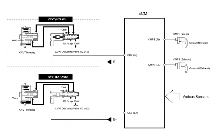
This system consists of
| –
| the
CVVT Oil Control Valve (OCV) which supplies the engine oil to the cam
phaser or runs out the engine oil from the cam phaser in accordance with
the ECM PWM (Pulse With Modulation) control signal, |
| –
| the CVVT Oil Temperature Sensor (OTS) which measures the engine oil temperature, |
| –
| and the Cam Phaser which varies the cam phase by using the hydraulic force of the engine oil. |
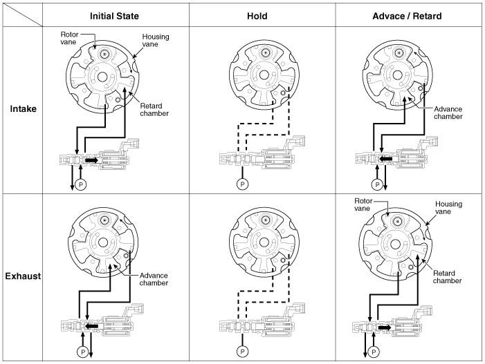
The
engine oil released from the CVVT oil control valve varies the cam
phase in the forward direction (Intake Advance/Exhaust Retard) or
opposite direction (Intake Retard/Exhaust Advance) of the engine
rotation by rotating the rotor connected with the camshaft inside the
cam phaser.
The
CVVT has the mechanism rotating the rotor vane by hydraulic force
generated by the engine oil supplied to the advance or retard chamber in
accordance with the CVVT oil control valve control.
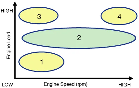
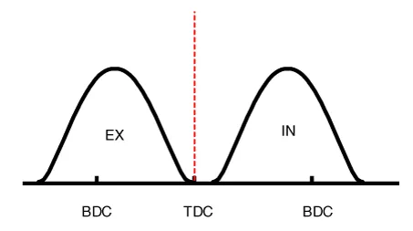
(1) Low Speed / Low Load
| (2) Part Load
|
 |
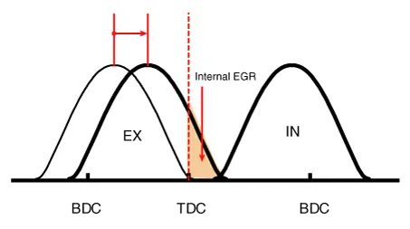 |
(3) Low Speed / High Load
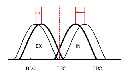
| (4) High Speed / High Load
|
 |
 |
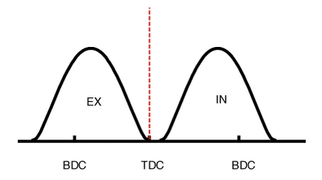
Driving
Condition
|
Exhaust Valve
|
Intake Valve
|
Valve
Timing
|
Effect
|
Valve
Timing
|
Effect
|
(1) Low Speed
/Low Load
| Completely
Advance
| * Valve Under-lap
* Improvement of combustion stability
| Completely
Retard
| * Valve Under-lap
* Improvement of combustion stability
|
(2) Part Load
| Retard
| * Increase of expansion work
* Reduction of pumping loss
* Reduction of HC
| Retard
| * Reduction of pumping loss
|
(3) Low Speed
/High Load
| Retard
| * Increase of expansion work
| Advance
| * Prevention of intake back flow (Improvement of volumetric efficiency)
|
(4) High Speed
/High Load
| Advance
| * Reduction of pumping loss
| Retard
| * Improvement of volumetric efficiency
|
Repair procedures
| 1. | Remove the cylinder head cover.
(Refer to Cylinder Head Assembly - “Cylinder Head Cover”)
|
| 2. | Remove the vacuum pump.
(Refer to Cylinder Head Assembly - "Vacuum Pump")
|
| 3. | Remove the timing chain.
(Refer to Timing System - “Timing Chain”)
|
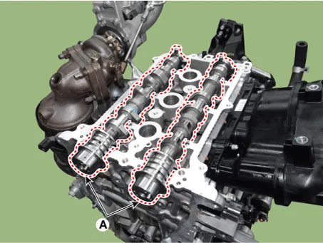
| 4. | Remove the intake CVVT assembly (A) and exhaust CVVT assembly (B).
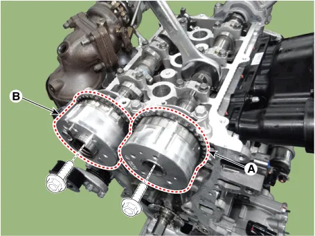 When removing the CVVT assembly hold the camshaft with a wrench to prevent the camshaft from rotating. |
|
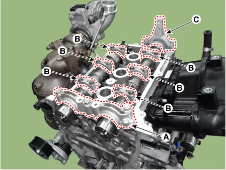
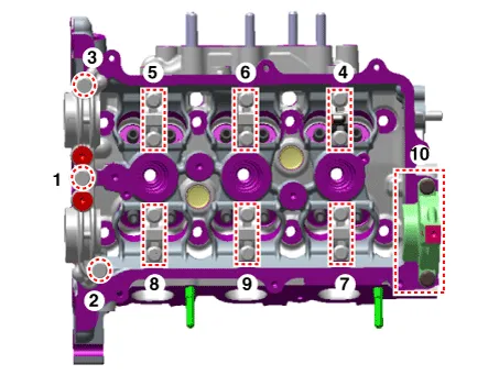
| 5. | Remove
the camshaft front bearing cap (A), camshaft middle bearing cap (B),
and camshaft rear bearing cap (C) in the sequence shown.
 |
| 6. | Remove the camshafts (A).
 |
Camshaft
| 1. | Inspect cam lobes. Using a micrometer, measure the cam lobe height.
Cam height
Intake : 41.79824 mm (1.6456 in) Exhaust : 41.57000 mm (1.6366 in) |
 If the cam lobe height is less than standard, replace the camshaft. |
| 2. | Inspect the camshaft journal clearance. | (1) | Clean the bearing caps and camshaft journals. |
| (2) | Place the camshafts on the cylinder head. |
| (3) | Lay a strip of plastigage across each of the camshaft journals.
 |
| (4) | Install
the camshaft front bearing cap (A), camshaft middle bearing cap (B),
and camshaft rear bearing cap (C) in following method by tightening to
the specified torque.
Tightening torque :
Step 1 A : 9.8 N·m (1.0 kgf·m, 7.2 lb·ft) B : 5.9 N·m (0.6 kgf·m, 4.3 lb·ft) Step 2 A : 18.6 - 22.6 N·m (1.9 - 2.3 kgf·m, 13.7 - 16.6 lb·ft) B : 11.8 - 13.7 N·m (1.2 - 1.4 kgf·m, 8.7 - 10.1 lb·ft) C : 11.8 - 13.7 N·m (1.2 - 1.4 kgf·m, 8.7 - 10.1 lb·ft) |
 Do not turn the camshaft. When cam caps are installed, the arrows on top of caps must point outward from the engine. |
|
| (5) | Remove the bearing caps. |
| (6) | Measure the plastigage at its widest point.
Camshaft bearing oil clearance
Intake : 0.027 - 0.057 mm (0.0010 - 0.0022 in) Exhaust : 0.027 - 0.057 mm (0.0010 - 0.0022 in) |
 If the oil clearance is greater than maximum, replace the camshaft. If necessary, replace cylinder head. |
| (7) | Completely remove the plastigage. |
|
| 3. | Inspect the camshaft end play. | (1) | Install the camshaft (A).
|
| (2) | Install
the camshaft front bearing cap (A), camshaft middle bearing cap (B),
and camshaft rear bearing cap (C) in following method by tightening to
the specified torque.
Tightening torque :
Step 1 A : 9.8 N·m (1.0 kgf·m, 7.2 lb·ft) B : 5.9 N·m (0.6 kgf·m, 4.3 lb·ft) Step 2 A : 18.6 - 22.6 N·m (1.9 - 2.3 kgf·m, 13.7 - 16.6 lb·ft) B : 11.8 - 13.7 N·m (1.2 - 1.4 kgf·m, 8.7 - 10.1 lb·ft) C : 11.8 - 13.7 N·m (1.2 - 1.4 kgf·m, 8.7 - 10.1 lb·ft) |
Do not turn the camshaft. When cam caps are installed, arrows on the top of caps must point to out side of engine. |
|
| (3) | Using a dial indicator, measure the end play while moving the camshaft back and forth.
Camshaft end play :
Intake : 0.1 - 0.2 mm (0.0039 - 0.0078 in) Exhaust : 0.1 - 0.2 mm (0.0039 - 0.0078 in) |
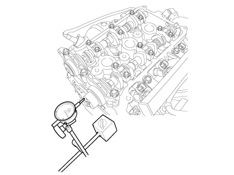 If the end play is greater than maximum, replace the camshaft. If necessary, replace cylinder head. |
|
CVVT (Continuous Variable Valve Timing) Assembly
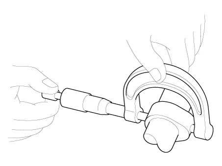
| 1. | Inspect the CVVT assembly. | (1) | Clamp the camshaft using a vise. Be careful not to damage the cam lobes and journals in the vise. |
| (2) | Check that the CVVT is locked by turning it clockwise or counterclockwise. It must not rotate. |
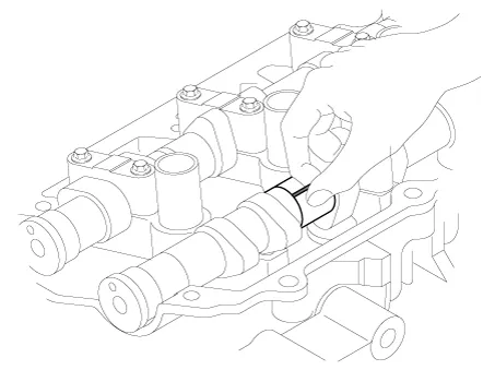
| (3) | Intake CVVT : Seal one of the two advance holes in the camshaft journal with tape. Exhaust CVVT : Seal one of the two retard holes in the camshaft journal with tape.
[Intake]
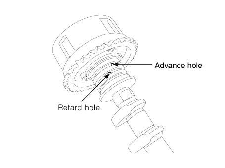
[Exhaust]
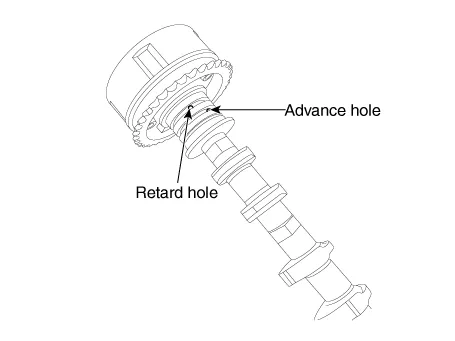 |
| (4) | Intake CVVT : Apply approx. 150 kPa (1.5 kgf/cm², 21 psi ) of compressed air into the unsealed advance hole to release the lock. Exhaust CVVT : Apply approx. 150 kPa (1.5 kgf/cm², 21 psi ) of compressed air into the unsealed retard hole to release the lock. Cover the oil paths with a piece of cloth when applying compressed air to prevent oil from spraying. |
|
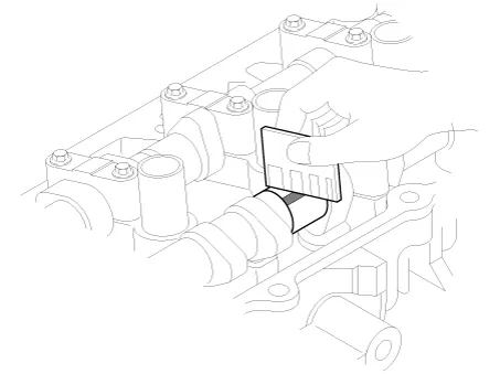
| (5) | Intake
CVVT : With compressed air applied, rotate the CVVT into the advance
direction (counterclockwise) within its phasing range and check that the
CVVT turns smoothly. Exhaust CVVT : With compressed air
applied, rotate the CVVT into the retard direction (clockwise) and check
that the CVVT turns smoothly.
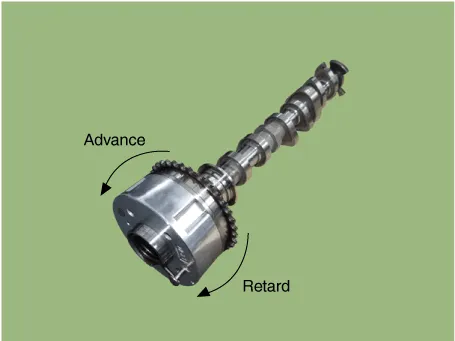
CVVT phasing range
Intake : 25° (from the most retarded position to the most advanced position) Exhaust : 20° (from the most advanced position to the most retarded position) |
|
| (6) | Intake CVVT : Rotate the CVVT into the most retarded position (clockwise) and then check that the CVVT is locked. Exhaust CVVT : Rotate the CVVT into the most advanced position (counterclockwise) and then check that the CVVT is locked. |
|
| 1. | Install the camshafts (A).
|
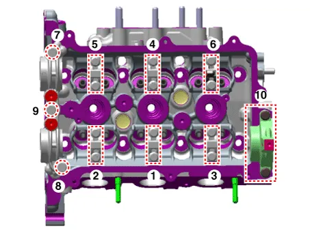
| 2. | Install
the camshaft front bearing cap (A), camshaft middle bearing cap (B),
and camshaft rear bearing cap (C) in the sequence shown.
Tightening torque :
Step 1 A : 9.8 N·m (1.0 kgf·m, 7.2 lb·ft) B : 5.9 N·m (0.6 kgf·m, 4.3 lb·ft) Step 2 A : 18.6 - 22.6 N·m (1.9 - 2.3 kgf·m, 13.7 - 16.6 lb·ft) B : 11.8 - 13.7 N·m (1.2 - 1.4 kgf·m, 8.7 - 10.1 lb·ft) C : 11.8 - 13.7 N·m (1.2 - 1.4 kgf·m, 8.7 - 10.1 lb·ft) |
|
| 3. | Install the intake CVVT assembly (A) and exhaust CVVT assembly (B).
Tightening torque :
63.7 - 73.5 N·m (6.5 - 7.5 kgf·m, 47.0 - 54.2 lb·ft) |
When installing the CVVT assembly hold the camshaft with a wrench to prevent the camshaft from rotating. |
|
| 4. | Install the remaining parts in the reverse order of removal. |
Repair procedures
Removal and Installation
1.Disconnect the battery negative terminal.
2.Disconnect the wiring connectors and harness clamps and remove the connector brackets around the vacuum pump.
Repair procedures
Removal
•
Use fender covers to avoid damaging painted surfaces. •
To avoid damaging the cylinder head, wait until the engine coolant
temperature drops below normal temperature (20°C [68°F]) before removing
it.
Other information:
Components and components location
Component Location
1. Driver power window switch 2. Assist power window switch 3 . Body Comtrol Module (BCM) 4 . Door lock knob 5 . Tailgate actuator 6. Door latch lock actuator 7 . Door lock/unlock switch 8 .
Repair procedures
Replacement
1.Disconnect the negative (-) battery terminal.
2.Remove the heater unit.
(Refer to Heater - "Heater Unit")
3.Remove the heater core cover (A) after loosening the mounting screws.
4.Pull out the heater core (A) from the heater unit.


