Kia Picanto (JA): Cruise Control System / Cruise Control Switch
Components and components location
| Components |
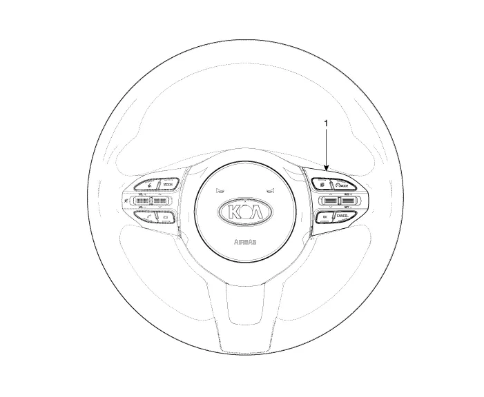
| 1. Right Remote Control Switch (Cruise+Trip Computer) |
Schematic diagrams
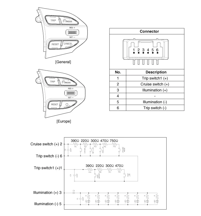
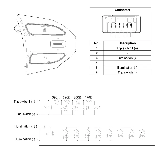
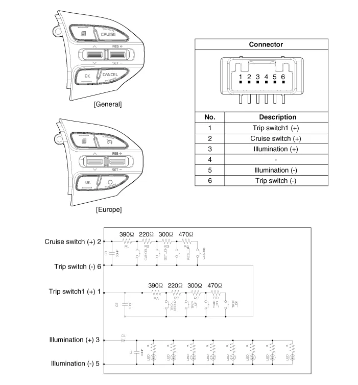
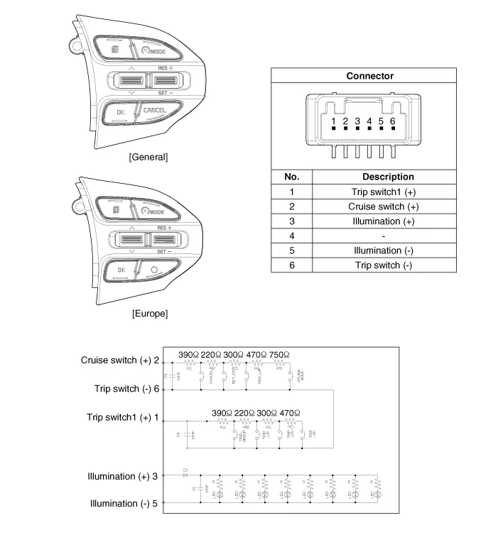
| Circuit Diagram |
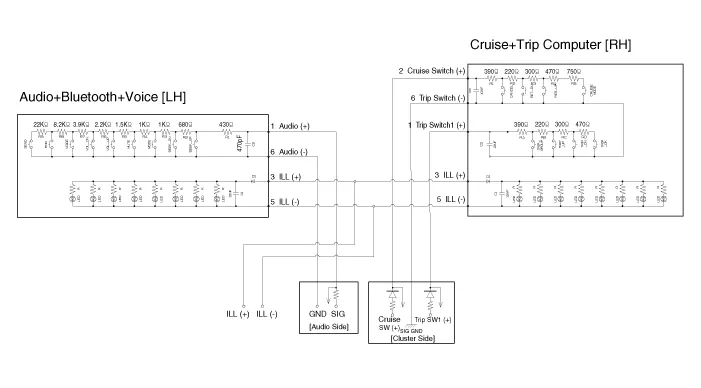
| [Trip (2 Button) + SEG LCD Cluster] |
| [Trip (2 Button) + ACC + Cruise] |
| [Trip (2 Button) + ACC + Cruise + SLD] |
| [Trip (4 Button) + DOT&TFT LCD Cluster] |
| [Trip (4 Button) + ACC + Cruise] |
| [Trip (4 Button) + ACC + Cruise + SLD] |
Repair procedures
| Removal |
| 1. | Disconnect the negative (-) battery terminal. |
| 2. | Remove the steering wheel assembly.
(Refer to Steering System - "Steering Wheel")
|
| 3. | Remove the steering wheel remote control (A) after loosening the mounting screws.
|


| 4. | Disconnect the steering wheel remote control connector (A).
|

| Installation |
| 1. | Connect the steering wheel remote control connector. |
| 2. | Install the steering wheel remote control. |
| 3. | Install the steering wheel and driver airbag module. |
| 4. | Connect the negative (-) battery terminal. |
| Inspection |
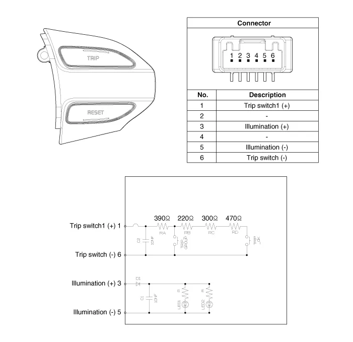
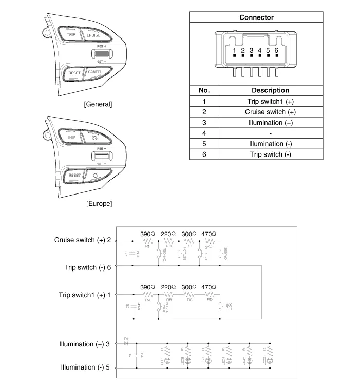
| 1. | Check for resistance between terminals in each switch position.
[RH : Cruise + Trip]
|

Description and operation Description The cruise control system is engaged by the cruise "ON/OFF" main switch located on right of steering wheel column.
Specifications Specifications Purge Control Solenoid Valve (PCSV) ▷ Specification Item Specification Coil Resistance (Ω) 18.
Other information:
Kia Picanto (JA) 2017-2026 Service & Repair Manual: Electro Chromic Inside Rear View Mirror
Components and components location Components Description and operation Description The ECM (Electro Chromatic inside rear view Mirror) is one that automatically dims to protect the driver’s eyes when it senses light reflecting from the car behind.
Kia Picanto (JA) 2017-2026 Service & Repair Manual: Windshield Wiper-Washer Switch
Repair procedures Removal 1.Disconnect the negative (-) battery terminal. 2.Remove the steering column upper and lower shrouds after loosening the screws. (Refer to Body - "Steering Column Shroud Panal") 3.Disconnect the wiper switch / washer switch connector (A).
Categories
- Manuals Home
- Kia Picanto Owners Manual
- Kia Picanto Service Manual
- Cylinder Head
- Heating,Ventilation, Air Conditioning
- Suspension System
- New on site
- Most important about car
